Introduction
This guide and subsequent guides will step you through the process of building the Power and Processing Module (PPM).
Attached at the bottom of the guide is the wiring diagram PDF if you want to use that as you go through building it to help identify where each wire goes.
-
-
Grab the Acrylic Support Plate supplied in the kit
-
Remove the protective film
-
-
-
Unbox the Dynamite ESC's
-
We need to make some modifications to the ESC's to get them to fit
-
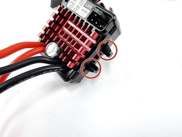
Remove the mounting brackets from both sides of the ESC. To remove push down on the mount it will click and come away from the ESC
-
Do this for both sides of both ESC's
-
-
-
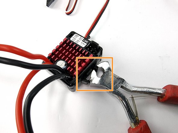
We need to remove the support pieces that the mounts fitted into.
-
Using a pair of pliers or side cutters grab one of the pieces of plastic to be removed and twist it to one side to break it away from the ESC
-
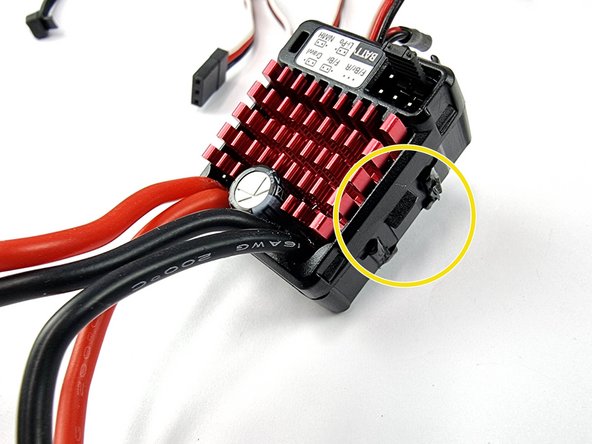
It doesn't have to be completely removed as long as the bulk of it is removed it will allow the ESC's to fit side by side in the mount.
-
Complete this on both sides of both ESC's
-
-
-
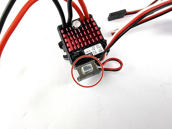
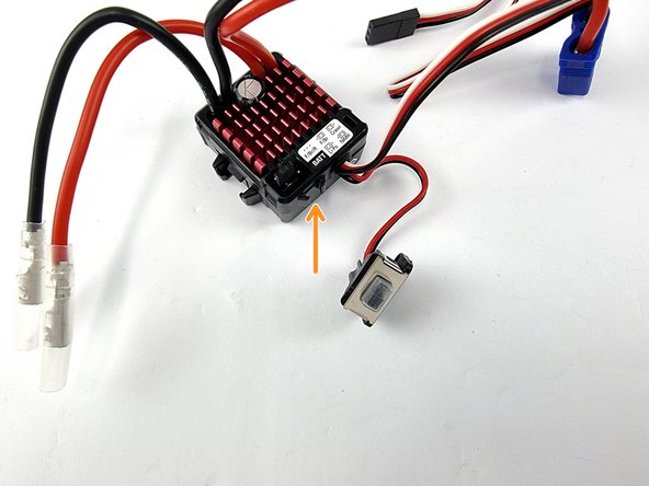
The ESC's have a power switch which for the Submarine isn't much use because it won't be easily accessible to us.
-
We want to remove the switch to save some space and make it easier to fit into the PPM
-
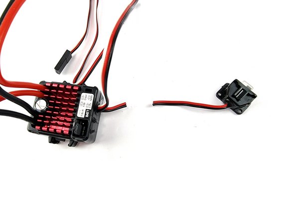
To remove the switch lift it up away from the ESC it it will slide out
-
-
-
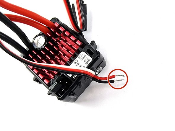
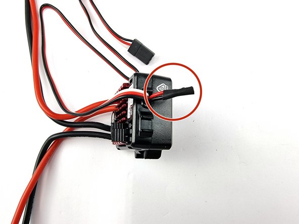
Cut the switch off the ESC leaving enough wire on the ESC for us to solder the 2 wires together so that the ESC is always on.
-
Strip the insulation back on the 2 wires
-
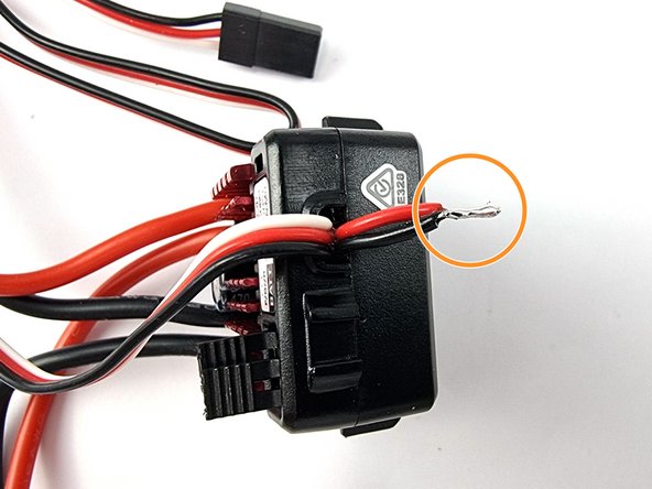
Twist the wires together and then solder them to bond them together.
-
-
-
With the 2 wires soldered together. Add a piece of heat shrink to cover the exposed wire and heat it up to shrink into onto the wires
-
Do the same for the second ESC
-
-
-
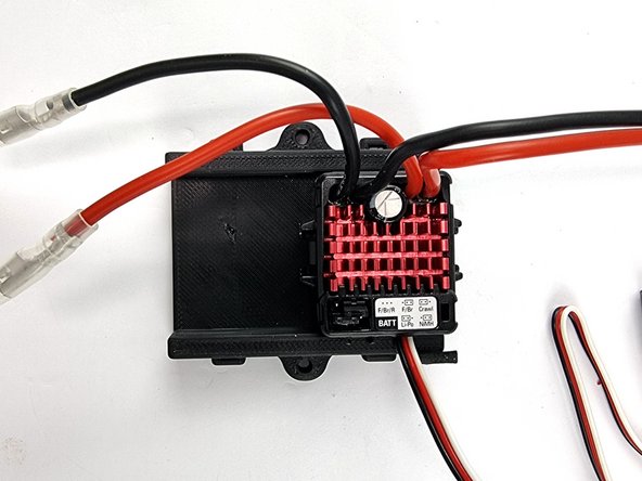
Grab the ESC Mount that you have 3D Printed. Both the ESC's will be mounted into this.
-
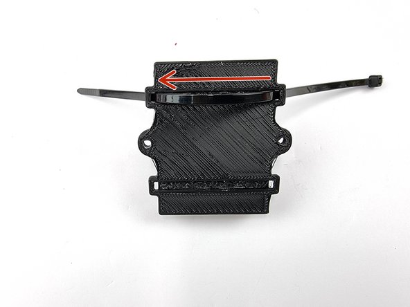
The secure the ESC's in place we use a cable tie. There is slots running underneath the mount for running the cable tie through.
-
Feed the cable tie through the slot from underneath
-
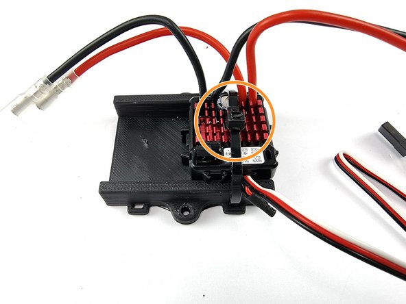
Position the ESC in place And tighten the Cable tie to secure the ESC
-
Ensure you remove the excess of the cable tie.
-
Repeat the steps to mount the second ESC into the mount
-
-
-
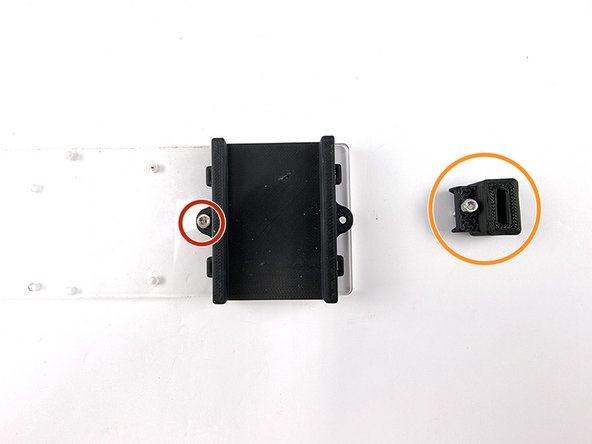
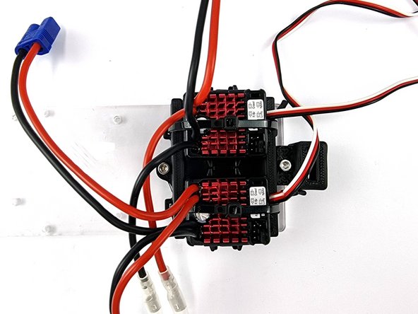
We can now mount the ESC's in their mount to the Support Plate
-
The first photo doesn't have the ESC's mounted to their mount to make it easier to see how it's mounted
-
Position the mount on the support plate where the engraved outline is for the Ballast ESC's.
-
Insert an M3 x 8mm Socket Head Cap Screw into the hole on the left and screw it down.
-
For the hole on the right we use an M3 x 12mm Screw and also need to position the EC3 Holder onto the mount before putting the screw through both.
-
With the EC3 Mount positioned insert the screw and tighten
-
-
-
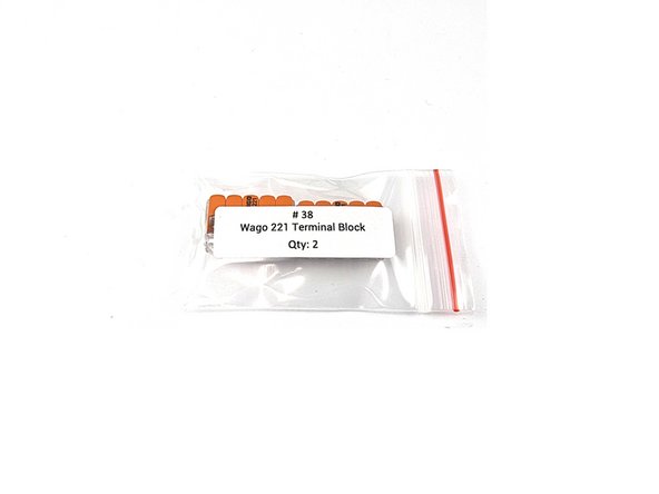
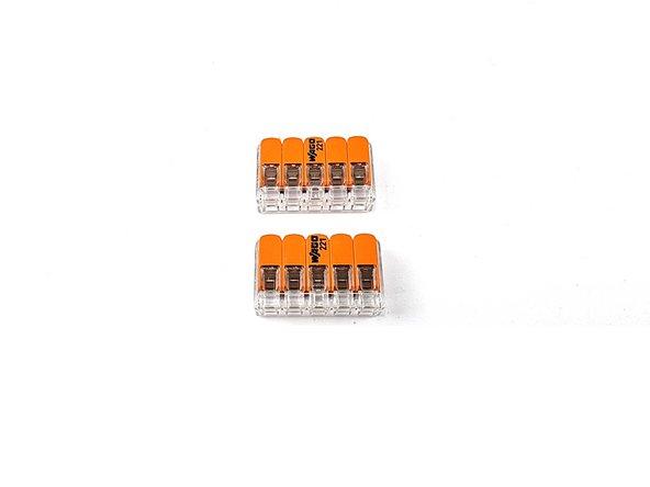
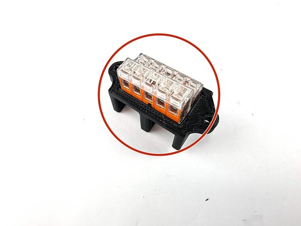
Find the bag with the 2 Wago 221 Terminal blocks in it
-
The Wago 221 is a splicing connector that joins wires together. It allows easy insertion and removal of wires.
-
We use these to join all the Positive wires together and all the negative wires together.
-
-
-
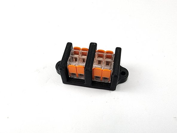
Grab the Wago mount that you have 3D Printed
-
Turn it upside down and insert the 2 Wago 221 connectors as shown
-
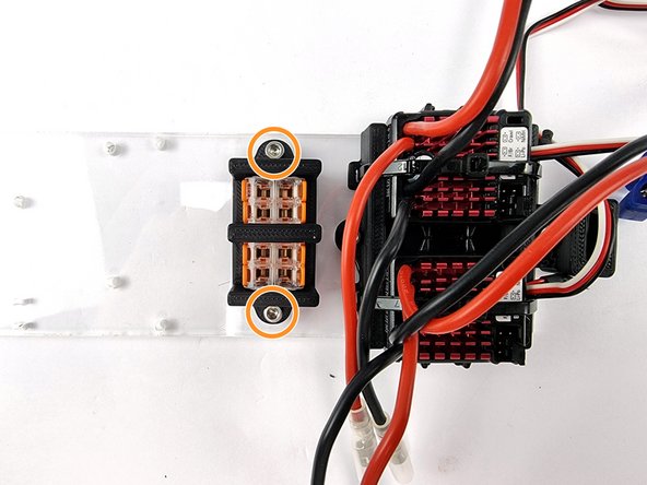
Place the mount with connectors inserted onto the support plate next to the ESC mount
-
Secure it with 2 x M3 x 8mm Socket Head Cap Screws
-
-
-
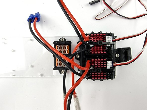
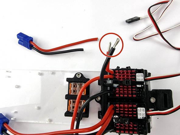
We need to connect the 2 ESC's to the Wago 221 connectors. We will cut the EC3 connector from the ESC's
-
Trim the positive and negative wires to length. They need to be long enough to reach into the bottom of the wago 221 connectors
-
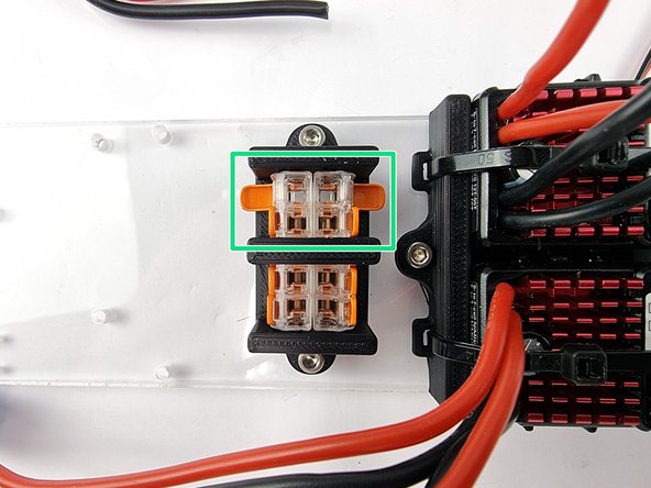
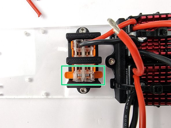
Pull out the 2 levers on the Wago 221 connectors as shown
-
-
-
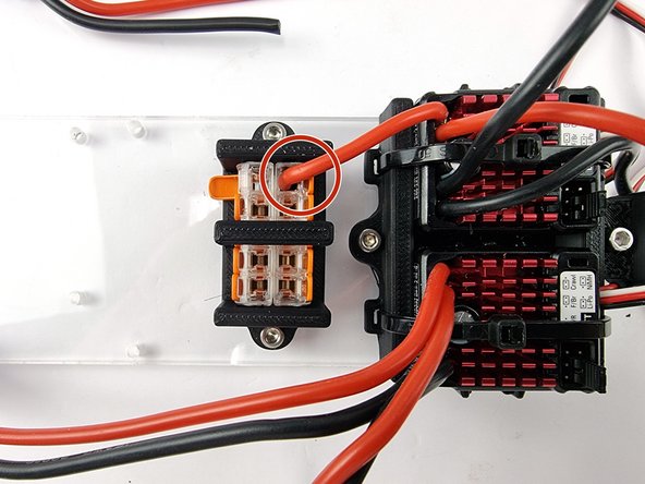
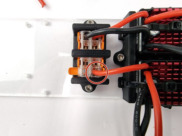
Insert the positive wire into one of the connectors. Ensure it is pushed in all the way and lift up the lever to lock the wire into place.
-
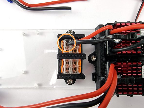
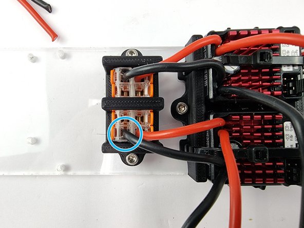
Insert the negative wire into the other Wago 221 connector
-
It doesn't matter which Wago 221 connector you use for the positive or negative wires. But it is important that you keep all the positive in the one connector and negative in the other connector. Do Not mix positive and negative wires in the same connector. You will cause damage if you do
-
-
-
Now to install the power wires for the second ESC. Trim the wires to length.
-
Open the 2 levers on the Wago 221 connectors as shown
-
Insert the positive wire into the connector that has the positive wire from the first ESC and close the lever to lock it into place
-
Insert the negative wire into the other connector and lift the lever to lock the wire into place
-
-
-
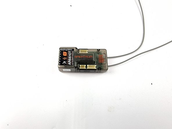
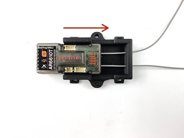
Find and unbox the Spektrum AR6610T Receiver that comes included in the kit
-
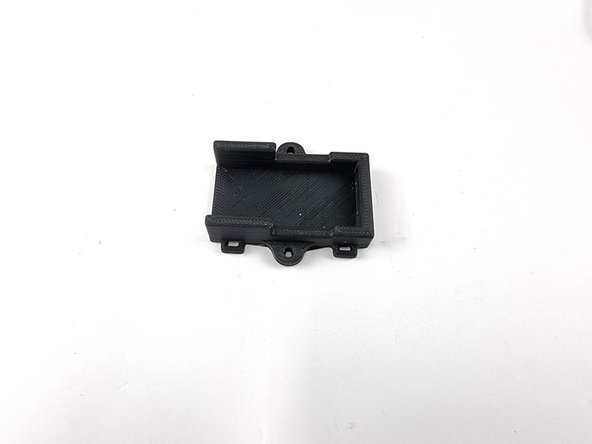
Grab the Receiver mount that you have 3D Printed.
-
Feed the aerials through the holes in the mount and slide the receiver into the mount
-
-
-
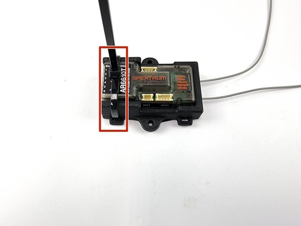
Install a cable tie on the left of the mount using the slot to feed the cable tie through.
-
You can add a cable tie on the right side as well if you like but not required. If you do it covers the button that is used to bind the receiver with the transmitter so can make it harder to get to that button when you need it.
-
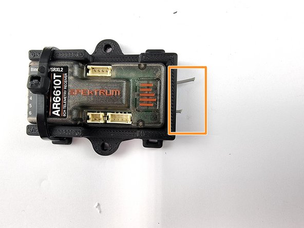
Trim the cable tie and also the aerials down
-
The aerials aren't required as we have the satellite receiver that is in the buoy that floats on the surface of the water. The signal that is used in the radios these days are digital and they won't penetrate water at all that's why we need to run the satellite receiver in a buoy.
-
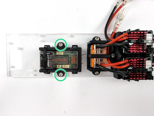
Install the receiver mount to the left of the Wago 221 connectors. Use 2 M3 x 8mm Socket Head Cap Screws to secure it to the support plate
-
-
-
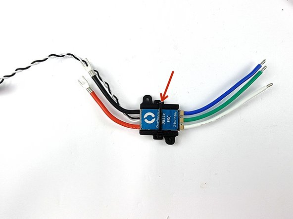
Mount the Blue Robotics ESC to the 3D Printed mount
-
Use a cable tie to secure it to the mount
-
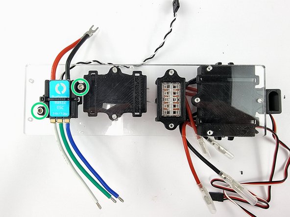
Place the ESC in the mount on the underneath side of the support plate
-
Insert 2 x M3 x 8mm Socket Head Cap Screw to secure it to support plate
-
-
-
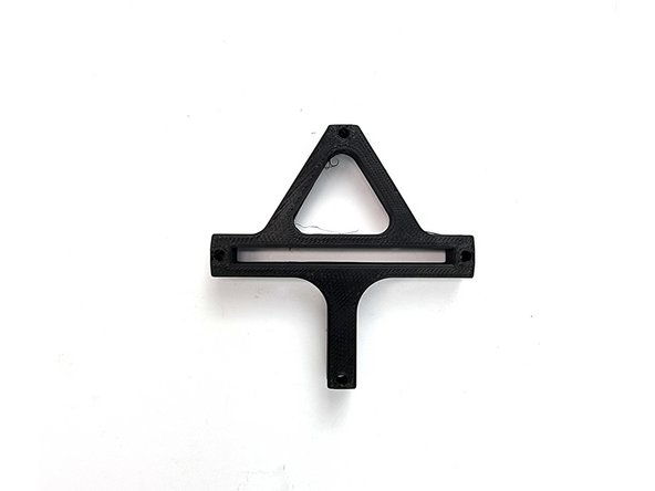
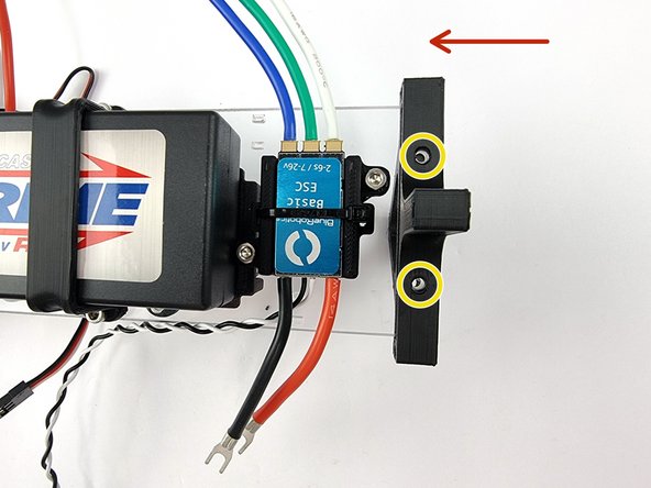
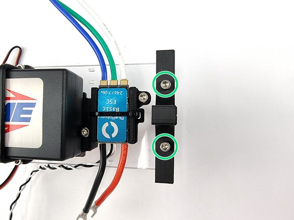
Grab the 3D Printed Support Plate Mount
-
Slide it onto the end of the support plate with the triangle section to the top.
-
Align the holes in the mount with the threaded holes of the support plate
-
Insert 2 x M3 x 8mm Socket Head Cap Screws to secure it to the support plate
-
-
-
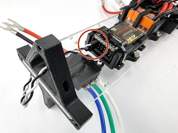
Feed the black and white wire from the thruster ESC through the triangle hole in the support plate mount.
-
Insert the plug into Channel 1 of the Receiver
-
The negative wire (Black Wire) should be at the bottom. Orientate the connector correctly before inserting.
-


