Video Overview
-
-
Welcome. You would have completed your model to this stage, thus far.
-
We will now insert the axle holes and support structures around them.
-
-
-
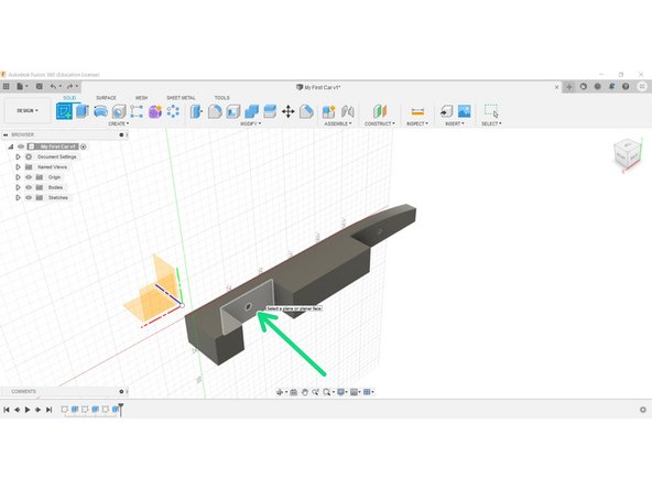
Create a New Sketch on the shown planar face in the rear wheel housing recess.
-
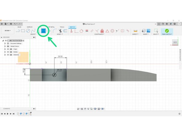
Select the Circle tool and Centre circle diameter from the Sketch menu.
-
Place a 6mm circle on the planar face/surface, as close to the centre as you can.
-
-
-
Select Sketch Dimension and position your circle centre 11.5mm from the top of your model (Y-axis), and 20.5 from one side.
-
This will position your axle hole centrally within the space.
-
These types of dimensions are called constraints, and they keep your geometry in place in case of accidental moving later on.
-
-
-
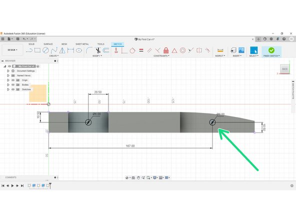
Repeat the process positioning the front axle at X167mm, Y10.5mm from the origin.
-
The axle hole is again 6mm in diameter.
-
-
-
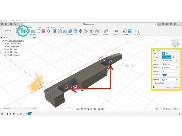
Select the Extrude tool.
-
Select both circles using the Shift key.
-
Cut to a depth of -10mm.
-
-
-
Create a new sketch on the inner planar face of the wheel well recess.
-
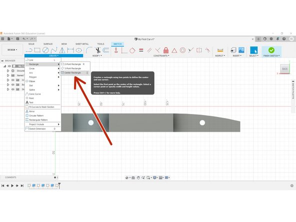
Select the Centre Rectangle from the Create tab dropdown.
-
This is a special rectangle that is located around a centre point, such as the centre of the axle hole.
-
-
-
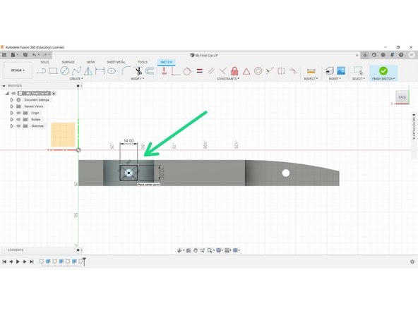
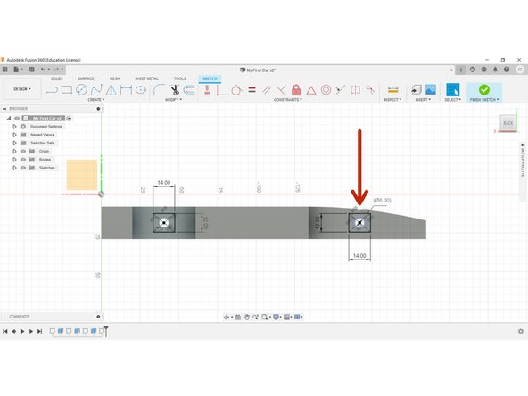
Create a Centre Rectangle at the centre of the axle hole.
-
The rectangle should be 14mm in width, and 12mm in height.
-
-
-
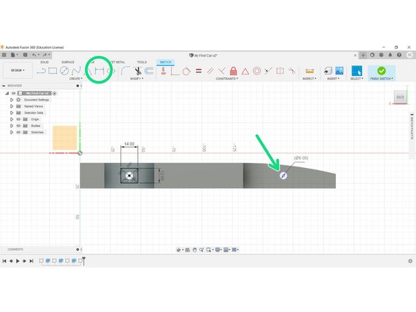
Use the Dimension tool to identify the second axle hole.
-
Place an identical Centre Rectangle over the front axle hole.
-
Click Finish Sketch
-
-
-
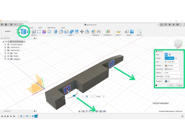
Extrude the axle supports outwards 2mm from the body.
-
Ensure the Extrude type is 'Join', and that the rectangles are 'joining' to the body, not 'cutting'.
-
-
-
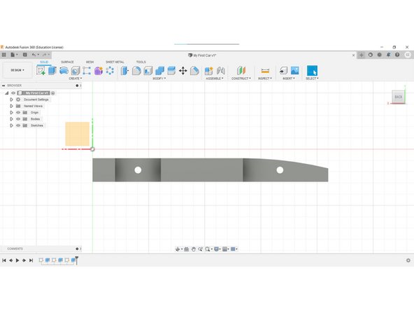
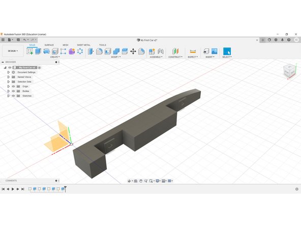
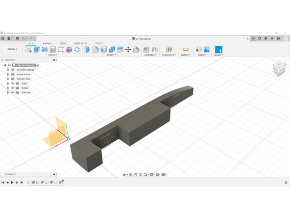
Congratulations, you have completed this stage.
-


