Introduction
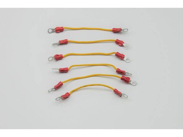
The next step is to wire the back of the switches. Two wires will make the “X” on the back of each switch that allows the motor to run in two
directions. Another set of wires allows power to be jumped from one switch to the other two switches.
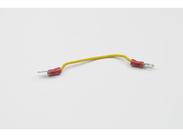
To make the Development Class ROV kit re-usable, ring connectors will be crimped on the ends of each wire. The ring connectors will be
screwed onto the back of the switch to make a solid connection. To construct the wires:
Tools
Parts
No parts specified.
-
-
Watch the informative video, taking note of the principles behind wire crimping and the techniques featured that can be applied to your ROV or Submarine build.
-
-
-
Cut six 6.5 cm lengths of 18-gauge wire.
-
Note that the colour of wire for wiring the back of the switch does not matter.
-
-
-
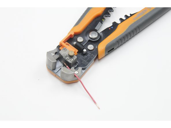
Strip .75 cm of wire of each end of the six wires.
-
-
-
When crimping the ring terminals onto the end of the wire, it is important to get a secure, metal to metal connection. If the ring terminal is not secured properly to the bare metal wire, electricity may not flow through the connection and your controller will not work. To make a secure crimp connection:
-
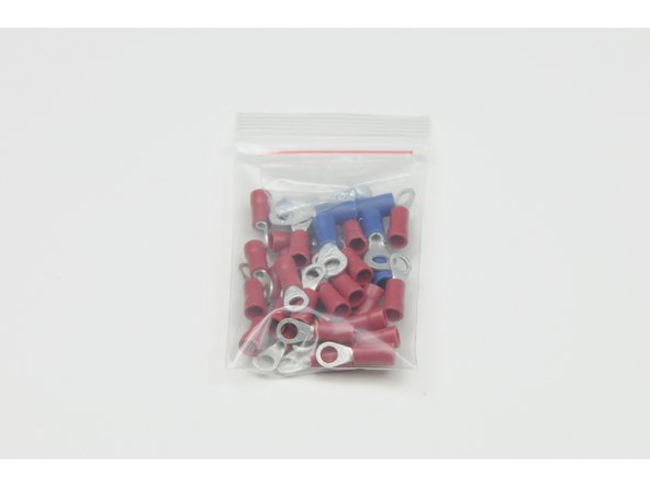
Twist the .75 cm of stripped wires. Insert them through the hole in the red ring terminal until they emerge 1 mm out of the metal ring.
-
-
-
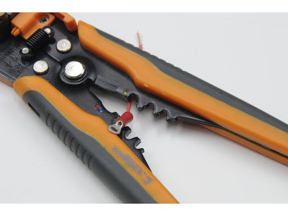
Use a crimping tool to crush the metal ring of the ring terminal over the stripped copper wire.
-
The connection should be metal to metal so electricity can flow freely.
-
The connection should also be physically secure so the wire cannot be pulled out ring terminal.
-
Repeat for both sides of all six wires.
-
Again, note the colour of the wires does not matter.
-


