-
-
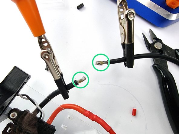
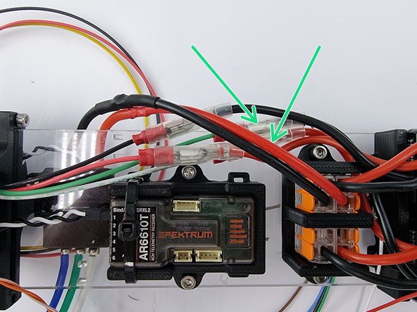
We need connect the power wires of the thruster ESC to the wago 221 terminal blocks
-
The supplied wires are too short so we need to extend them
-
Cut the supplied spade connector off the red wire and strip the insulation from the end of the wire.
-
Grab the supplied 14Awg red wire and strip the insulation from the end of the wire.
-
-
-
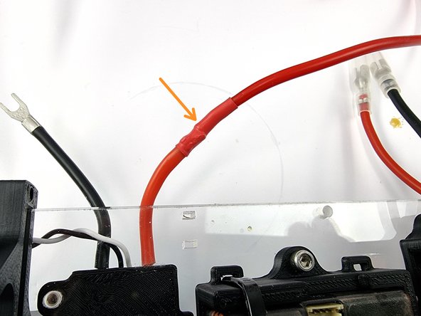
Cut a section of heat shrink and slip it onto the wire.
-
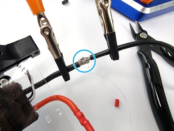
Tin both ends of the wires with solder to prepare them to be soldered together
-
Solder the 2 ends of the wires together
-
-
-
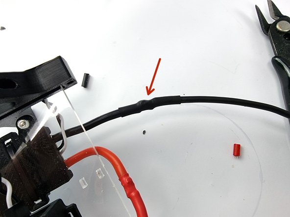
Slide the heat shrink over the soldered joint and apply heat to shrink it into place
-
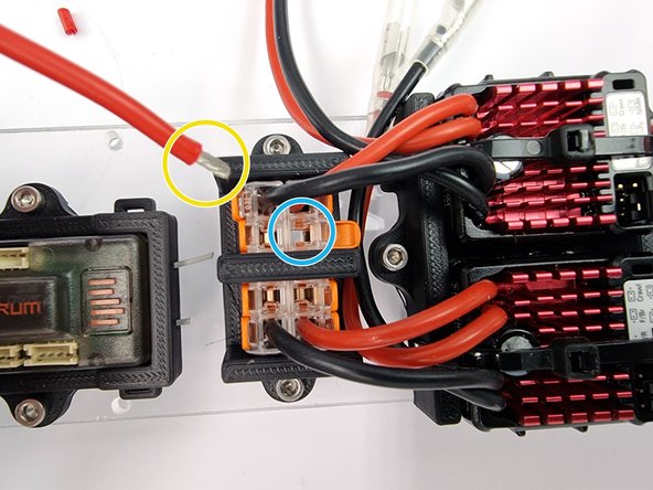
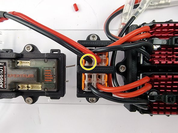
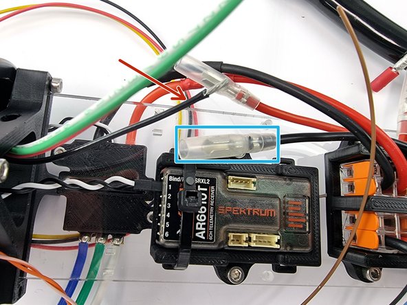
We need to cut the wire to the correct length. We are going to insert it into the vacant spot on the right hand Wago 221 at the top highlighted in blue. Measure out the correct length to allow the wire to reach the bottom of the Wago 221
-
Strip the insulation from the end of the wire
-
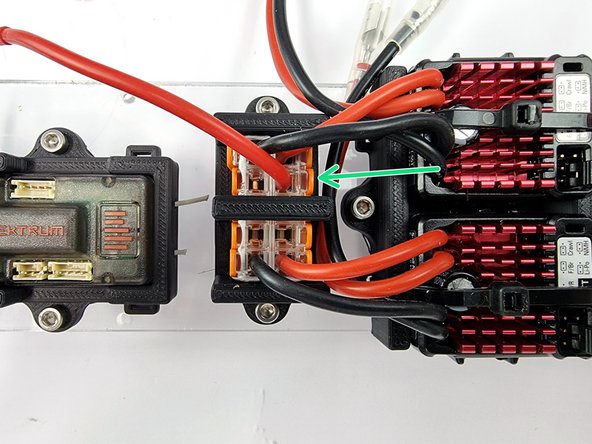
Insert the wire into the Wago 221 and close the lever to lock it into place
-
-
-
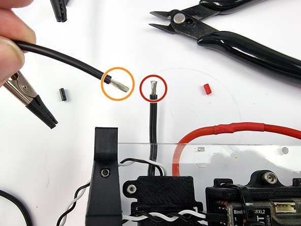
Cut the supplied spade connector off the black wire from the thruster ESC and strip the insulation from the end of the wire.
-
Grab the 16Awg black wire supplied in the kit and strip the insulation from the end of the wire.
-
Tin the 2 ends of the wires with solder to prepare them to be soldered togther.
-
Cut a section of heat shrink and slide onto one of the wires before you solder the 2 wires together.
-
Solder the 2 ends together to join the wires.
-
-
-
Slide the heat shrink over the soldered joint and heat to shrink it into place.
-
We need to cut the wire to the correct length. We are going to insert it into the vacant spot on the right hand Wago 221 at the top highlighted in blue. Measure out the correct length to allow the wire to reach the bottom of the Wago 221
-
Strip the insulation from the end of the wire.
-
Insert the wire into the Wago 221 and lift up the lever to lock it into place
-
-
-
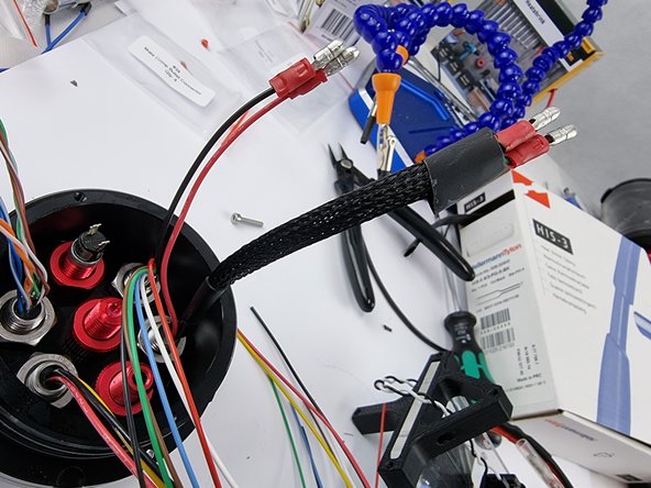
In the next steps we will be trimming the wires to length from the bulkhead connectors. To be able to accurately determine the length we need to cut them to its best to secure the support plate mount onto the end cap.
-
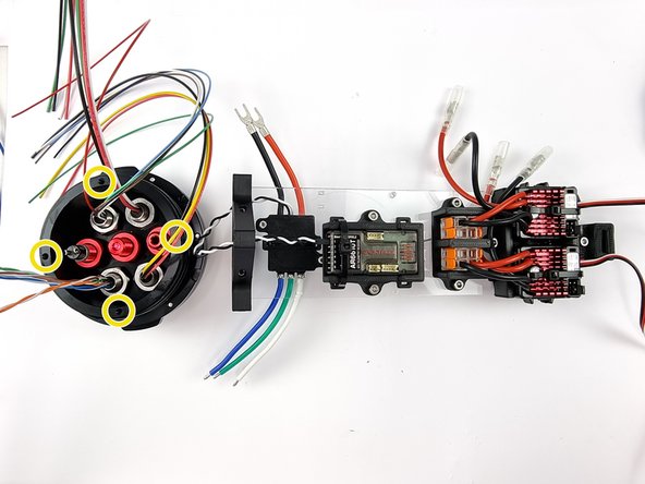
There are 4 threaded holes in the end cap that we use to secure the support plate mount to. We will be taking the end cap off a few times before we are finished so no need to install all 4 screws.
-
Use the M3 x 12mm screws secure the support plate mount to the end cap.
-
-
-
We will trim the wires from the 4 pin bulkhead first. These are the wires that run to the pumps in both ballast tanks.
-
Starting with the black wire from the 4 pin bulkhead. It will connect to the black wire from the top Dynamite ESC highlighted in blue.
-
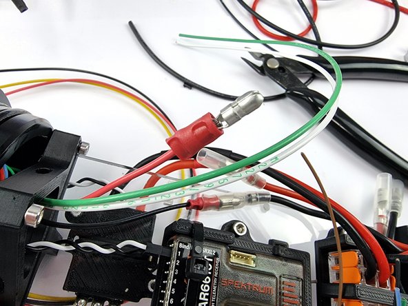
We need to trim it to length and then crimp on a male bullet connector. position the wires close together to gauge the length at which to cut the wire remembering that the bullet connector will add some length to it.
-
A tip to get a more accurate length is to fit the male bullet connector into the female connector before cutting the wire so you can see where the wire needs to come up to.
-
-
-
Slide the bullet connector onto the end of the wire.
-
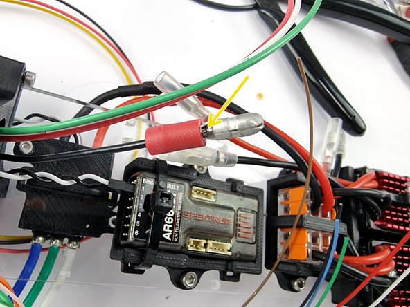
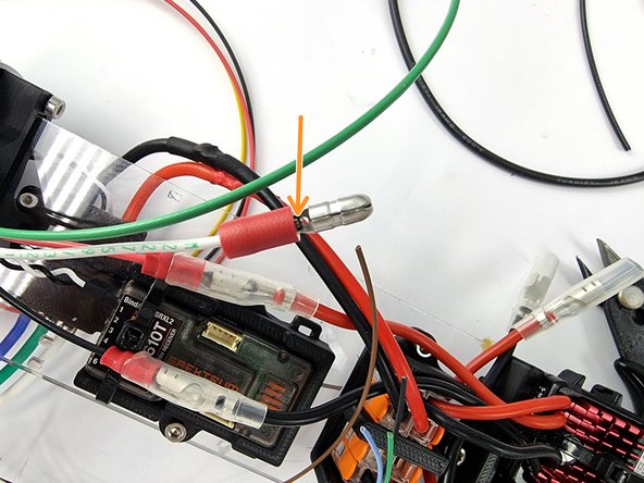
Ensure that the bare wire extends all the way into the connector so that the wires touch the metal stop you can see highlighted in the photo.
-
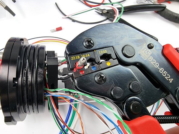
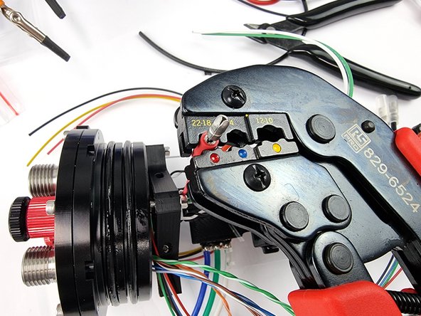
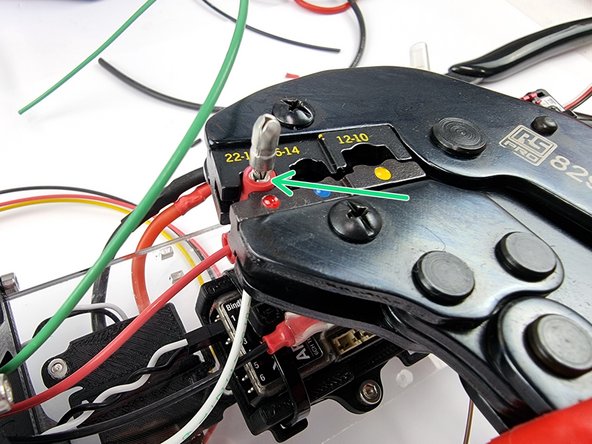
Now we need to crimp the connector to the wire. It helps to have a set of proper crimpers for this to ensure the wire doesn't pull out when disconnecting them.
-
-
-
Once crimped you can give the connector a tug to ensure it has been crimped on correctly. If it wants to slide off the wire you need to re-crimp it
-
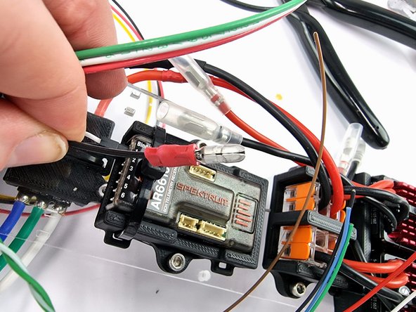
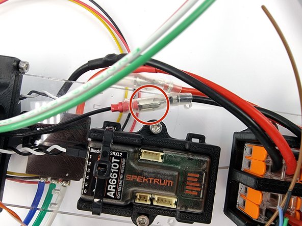
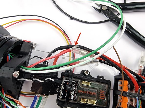
You can need push it into the female bullet connector from the Dynamite ESC
-
-
-
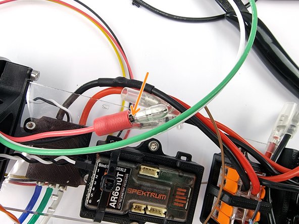
Cut the red wire to length allowing for the bullet connector to be crimped onto the end of the wire
-
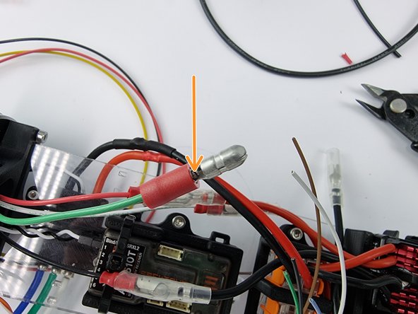
Slide a male bullet connector onto the wire ensuring the wire reaches the stop in the bullet connector.
-
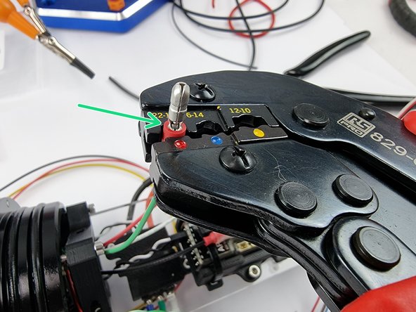
Once happy with the position of the bullet connector crimp it into place.
-
-
-
Once crimped you can give the connector a tug to ensure it has been crimped on correctly. If it wants to slide off the wire you need to re-crimp it
-
Now insert the connector into female bullet connector from the dynamite ESC
-
-
-
Next is the wiring for the second dynamite ESC
-
The white and green wires from the 4 pin bulkhead connector are used for the second dynamite ESC
-
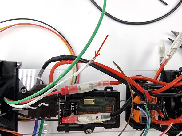
Trim the white wire to connect with the red wire from the ESC.
-
Slide a male bullet connector onto the wire. Check that it reaches all the way into the connector
-
Once happy with the fitment of the connector crimp it onto the wire.
-
-
-
Trim the green wire to connect with the black wire from the ESC.
-
Slide a male bullet connector onto the wire. Check that it reaches all the way into the connector
-
Once happy with the fitment of the connector crimp it onto the wire.
-
-
-
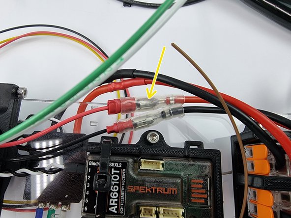
You can now insert the male bullet connectors into the female bullet connectors from the Dynamite ESC
-
Optional: You can use cable sleeving to protect the wires and neaten them.
-
-
-
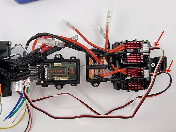
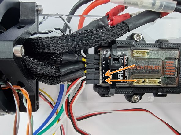
Now to connect the communication wires to the receiver.
-
Channel 5 and 6 on the receiver are the ports to connect the 2 Dynamite ESC's too
-
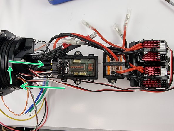
Rather then cutting the cables shorter you can direct them around the support plate mount to use up the extra length.
-
Almost done!
Finish Line


