-
-
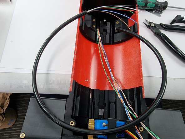
Insert the 8 Pin connector into the 8 pin bulkhead on the PPM.
-
Run the cable under the PPM and place into the cut outs in the hull supports.
-
Place the cable cover over the cable and insert the M3x8mm screws to secure it to the hull support
-
-
-
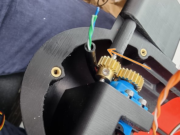
Feed the cable under the fore servo and place it into the groove in the bottom fore cap.
-
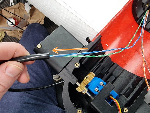
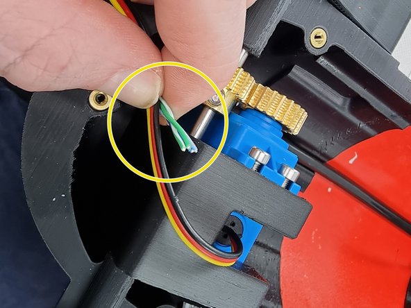
We need to remove the outside cable cover to allow the wires that will connect to the satellite receiver. Using a pair of cutters cut through the cable cover making sure not to cut any of the wires.
-
Slide the cut section of the cable cover away from the wires.
-
-
-
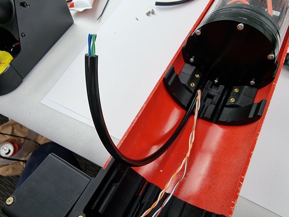
Find the trimmed section of cable from the 6 pin connector. We want to use the cable cover from it to slide over the wires running to the fore servo.
-
Trim the cable cover to length and slide it over the wires for the fore servo which are the blue,blue/white,green and green/white wires.
-
-
-
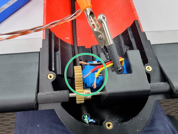
Feed the cable under the fore control surfaces shaft.
-
Position the wires to work out the postion to trim the wires from the servo to prepare to join them together.
-
Once the wires have been trimmed strip the insulation from the end of the wires.
-
-
-
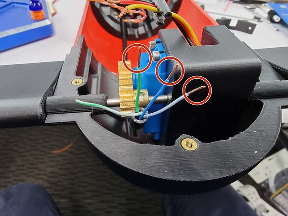
Strip the insulation from the blue, blue and white and green wires.
-
The Green/White wire is a spare wire that isn't required in the standard setup.
-
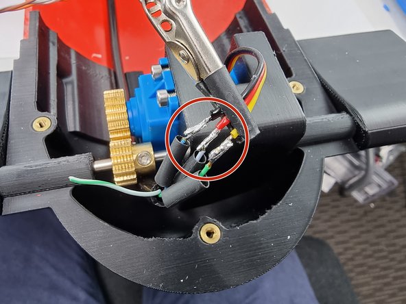
Tin the tips of the wires and slide a section of heat shrink onto each wire.
-
-
-
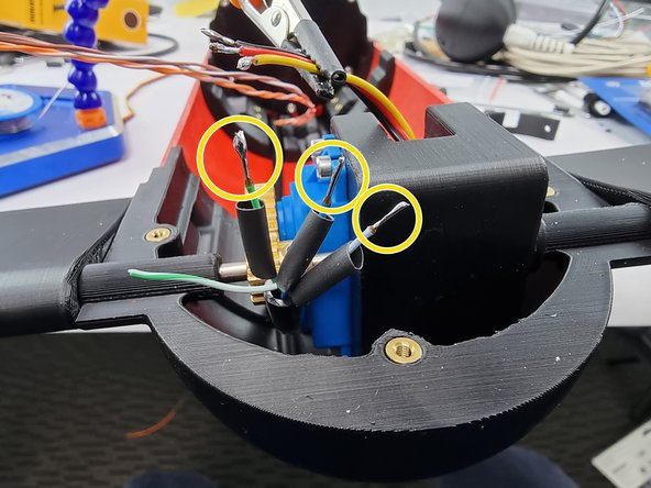
Solder the wires together in the following matchups.
-
Blue wire to Black wire. Blue/White wire to Red Wire and Green Wire to Yellow Wire
-
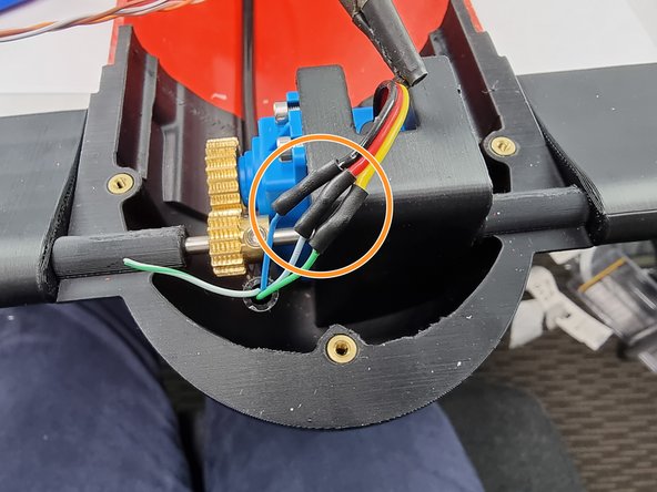
Slide the heat shrink over the soldered joints and apply heat to shrink them into place.
-
-
-
That completes the wiring for the Fore Cap
-