-
-
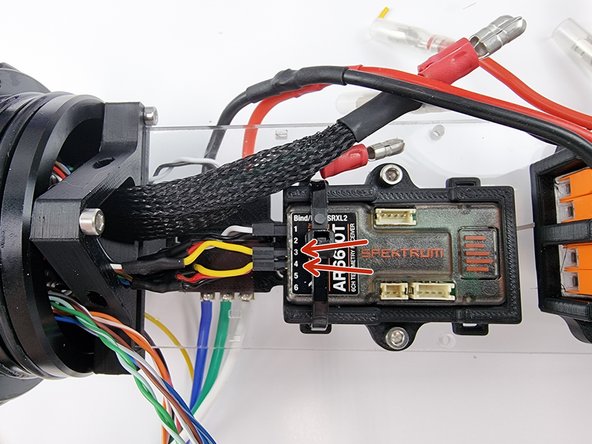
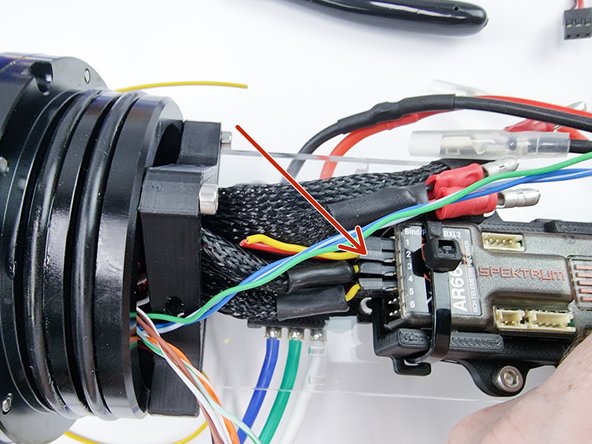
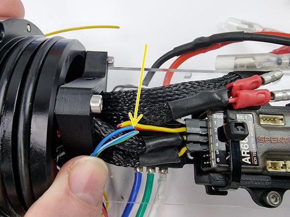
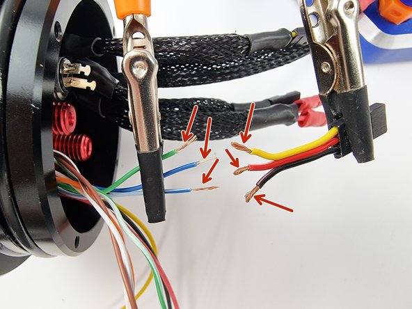
The 3 servos on the submarine are connected to the PPM through the cobalt connectors which ensure a waterproof connection. We will connect the PPM side first to the cobalt connector bulkhead.
-
The wires running to the servo will connect into the channels of the receiver in the PPM then travel through the relevant Cobalt connectors out to the servos.
-
We are essentially extending the wires with the cobalt connector in the middle. We need to cut off the connector from the servo so that we can plug it into the receiver and then trim the wire from the cobalt bulkhead and solder them together.
-
Cut the connector off leaving 3-4cm of wire from the connector to allow us to solder it to the cobalt bulkhead connector wires.
-
-
-
Insert the connector that was cut off servo into channel 3 of the receiver.
-
The rear servos are connected to the 6 pin cobalt connector.
-
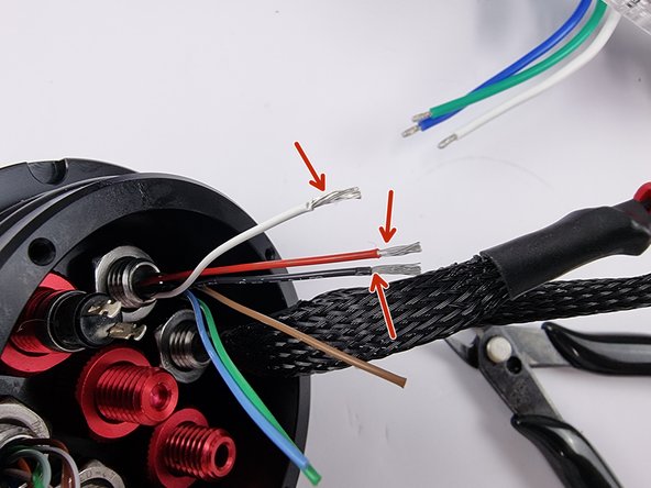
Grab the 6 wires from the 6 pin bulkhead. Align them with the wires from the connector we plugged into the receiver.
-
we need to trim the wires down to be soldered to the wires from the connector. line them up allowing for some space to solder them together and trim the wires to length.
-
-
-
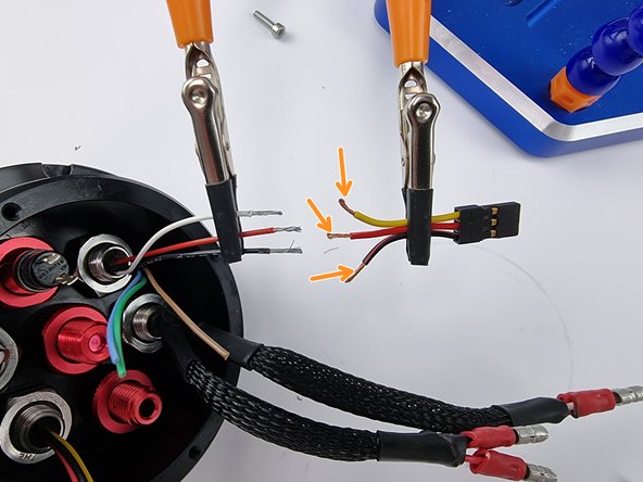
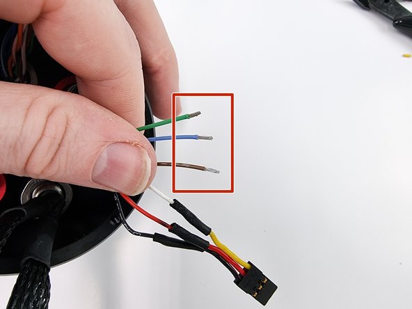
Once you have trimmed the wires we can strip the insulation from the end of the wires.
-
Strip the end of the wires on the connector as well. If possible it makes it easier if you can support both wires during the next steps to solder them together
-
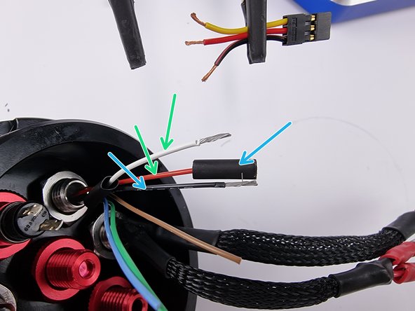
We will use the white, red and black wires for one of the servos and brown, green and blue wires for the second servo.
-
Cut small sections of heat shrink and place them onto the 3 wires.
-
-
-
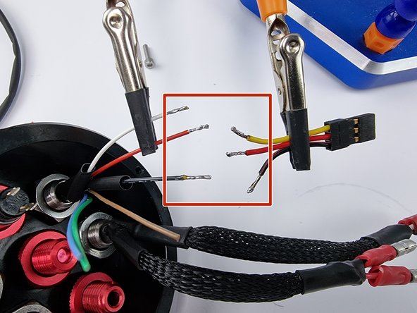
First we need to tin the wires with solder to prepare them for soldering together
-
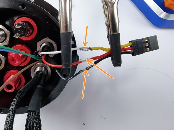
Now solder the wires together making sure the white wire is soldered to the yellow wire, the two red wires soldered together and the two black wires soldered together.
-
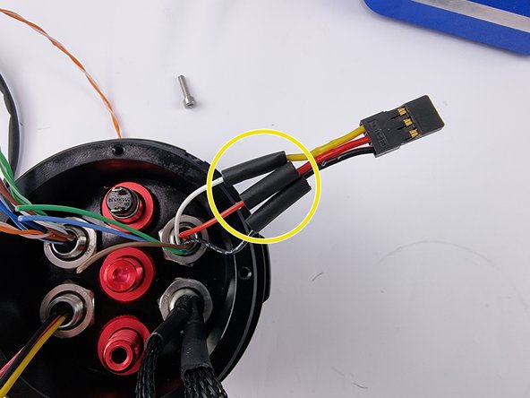
Allow the solder joints to cool then slide the heat shrink over the joints and apply heat to shrink them into place
-
-
-
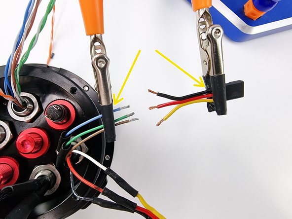
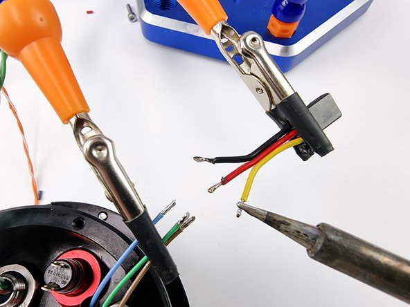
Next we can solder the connector for the other servo.
-
For this we use the green, blue and brown wires from the 6 pin bulkhead connector
-
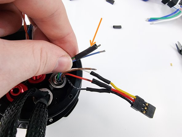
Before soldering the wires together cut some heat shrink and slide onto each wire.
-
If possible secure he wires in place before soldering them.
-
-
-
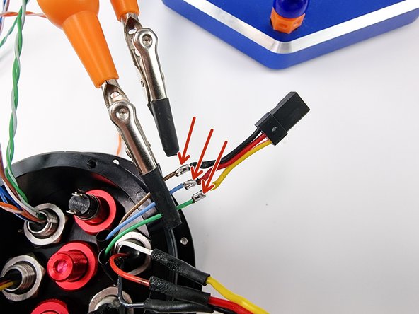
First tin the ends of each wire with solder
-
Solder the wires together ensuring that you join the brown wire to the black wire, blue wire to the red wire and the green wire to the yellow wire
-
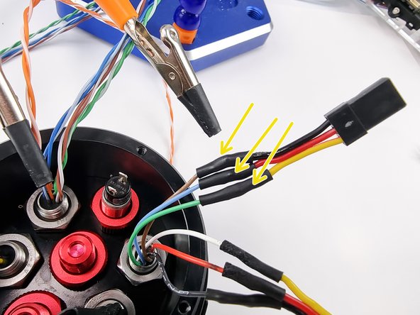
Slide the heat shrink over and apply heat to set it in place.
-
-
-
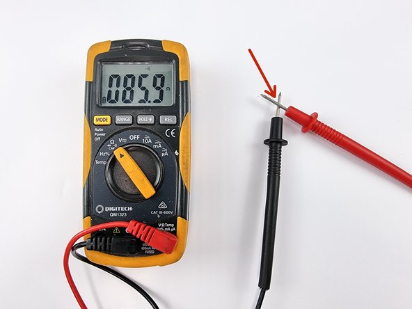
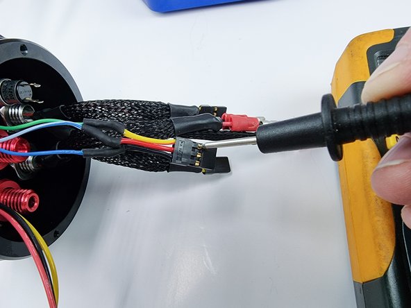
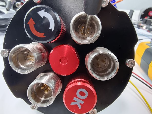
We can check the soldering connection of the wires using a multimeter in the continuity mode.
-
Set your multimeter to continuity mode where it buzzes when you touch the 2 probes together.
-
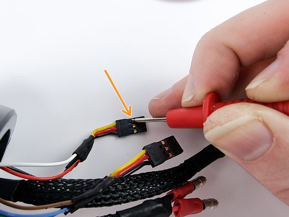
Touch one probe on one of the pins in the black connector that plugs into the receiver.
-
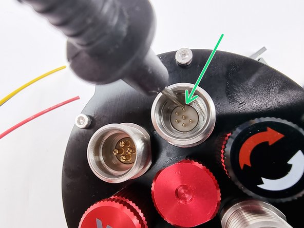
Touch the other probe on a pin in the 6 pin bulkhead connector. You will need to touch the probe on one pin at a time until you find the pin that is connected to the wire of the connector you are touching with the other probe.
-
If you touch every pin in the 6 pin bulkhead connector and it doesn't buzz, there are 2 possible issues the first is you aren't making contact with the pin in the black connector so check that and ensure it is making contact. The other issue will be in the soldered joint not making a connection. You will have to resolder that joint to fix it.
-
-
-
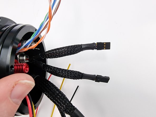
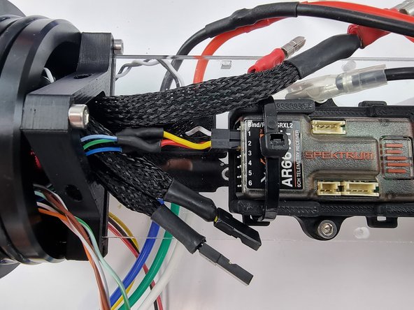
Once you have checked the connection of each wire with the multimeter and you are happy with the result you can sleeve the wires if you want.
-
-
-
Insert the connectors into channel 3 and channel 4 of the receiver
-
-
-
We will now solder the connector onto the wires from the servo in the fore cap. It is connected through the 8 pin bulkhead connector
-
We will use the blue, blue/white and green wires from the 8 pin bulkhead connector for the servo
-
Separate the 3 wires and plug in the connector that you have cut off the servo into the receiver.
-
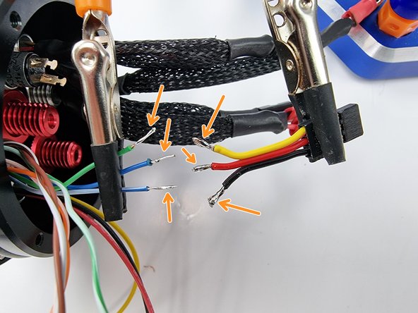
Trim the wires from the bulkhead connector to length to be soldered to the wires from the black connector in the receiver.
-
-
-
Strip the end of the wires to prepare them for soldering.
-
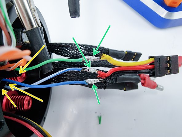
Tin the end of each wire with solder
-
Before soldering the wires together cut a section of heat shrink and slide onto one side of the wires.
-
Solder the wires together using these pairings. Green soldered to yellow, Blue/white soldered to red and blue soldered to black
-
-
-
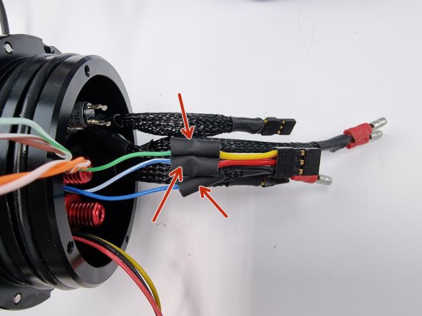
Once the wires have been soldered together and have been allowed to cool down slide the heat shrink over the soldered joint
-
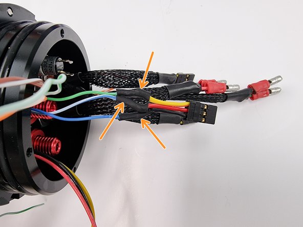
Apply heat to the heat shrink to shrink it over the soldered joint
-
-
-
Using a multimeter check the continuity across the pins on the black connector to the pins on the bulkhead connector to ensure a good solder joint has been made.
-
If you check all the pins and don't get the buzzing sound from the multimeter you will need to check the solder joint and re-solder it.
-
-
-
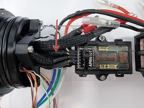
Plug the connector into channel 2 of the receiver.
-
You can sleeve the cable to neaten it up if you like but not required
-
-
-
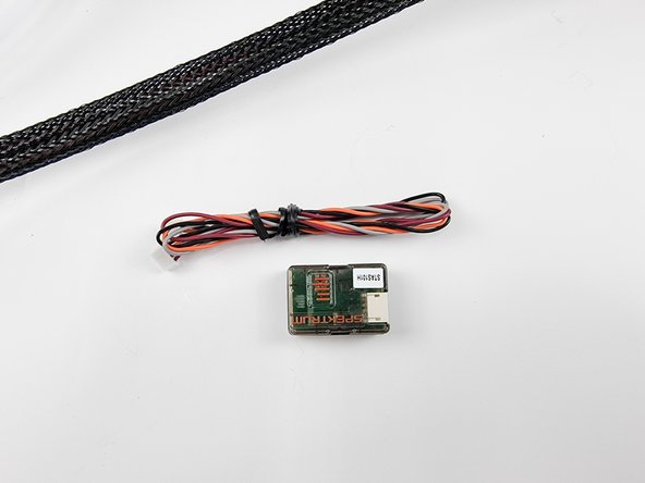
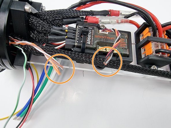
Unbox the satellite receiver. This will be put in the buoy that floats on the water surface to allow the controller to keep radio connection with the submarine. As once the sub submerges under the water surface the radio frequency will no longer be able to get to the receiver in the submarine due to it not being able to penetrate through the water.
-
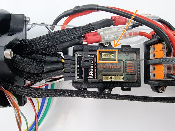
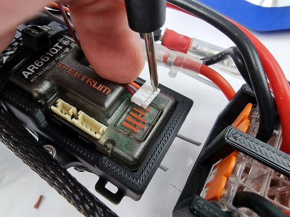
It plugs into the receiver using the top plug in the photo.
-
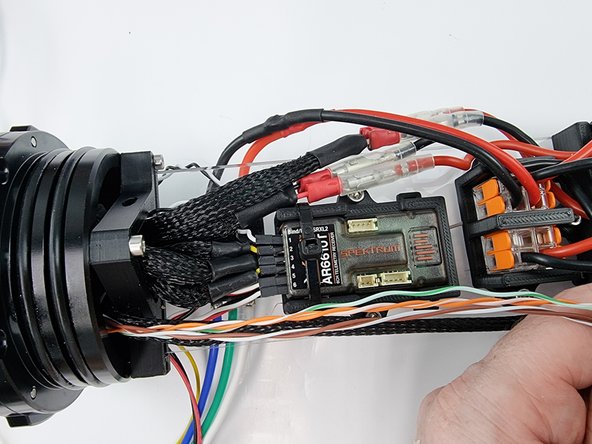
it connects through the 8 pin bulkhead connector with the fore servo.
-
-
-
We use the orange, orange/white, brown and brown/white wires to connect to the satellite receiver connector
-
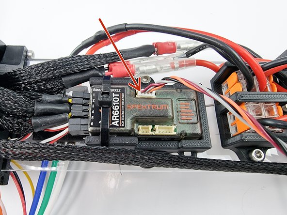
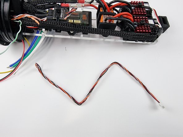
Plug the cable that comes with the satellite receiver into the port on the receiver.
-
Trim the wires to length allowing some slack so that when they are soldered together it is not tight to plug the connector in.
-
The green/white wire is not used and is a spare wire. you can tuck it into the end cap to keep it out of the way and it will be available if you make any changes and need an extra wire.
-
-
-
Keep the section of the cable you trimmed for the satellite receiver. We will need this to connect in the buoy.
-
-
-
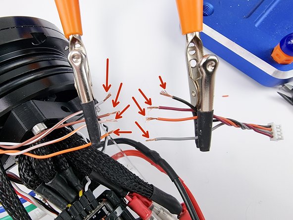
Strip the insulation from the end of the wires to prepare them for soldering
-
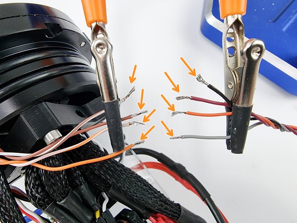
Tin the end of each wire before soldering them together
-
-
-
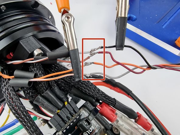
Before soldering the wires together cut strips of heat shrink and slide onto one side of the wires.
-
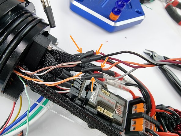
Solder the wires together with the following pairs. Brown/white soldered to black, brown soldered to maroon, orange soldered to orange and orange/white soldered to grey.
-
Once the wires have been soldered together and have cooled down slide the heatshrink over the soldered joints and apply heat to them to shrink them into place.
-
-
-
We can now check the continuity across each wire with a multimeter to ensure the soldered joints have made a good connection.
-
If you find an issue with any of the wires you will need to check the soldered joint and re-solder if required
-
Almost done!
Finish Line


