Tools
Parts
No parts specified.
-
-
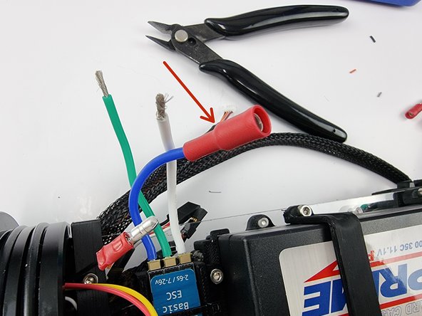
We need to connect the thruster ESC to the 3 pin bulkhead connector. You can solder the wires together or you can crimp bullet connectors on as shown in the next few steps. This allows you to disconnect if you need.
-
Trim the wires from the 3 pin bulkhead connector. We will start with the black wire. Trim it but allow enough length to add the bullet connector onto it.
-
-
-
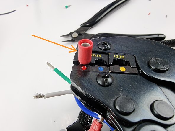
Fit a male bullet connector onto the black wire ensuring the wire is inserted all the way
-
Using a crimp tool crimp the connector onto the wire
-
Once crimped check the fit and ensure its not going to slide off the wire.
-
-
-
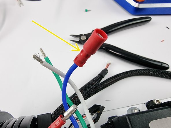
Slide a female bullet connector onto the blue wire from the thruster ESC
-
Crimp onto the wire ensuring the wire is inserted all the way into the connector
-
Once crimped give the connector a tug to ensure that it won't slide off the wire
-
-
-
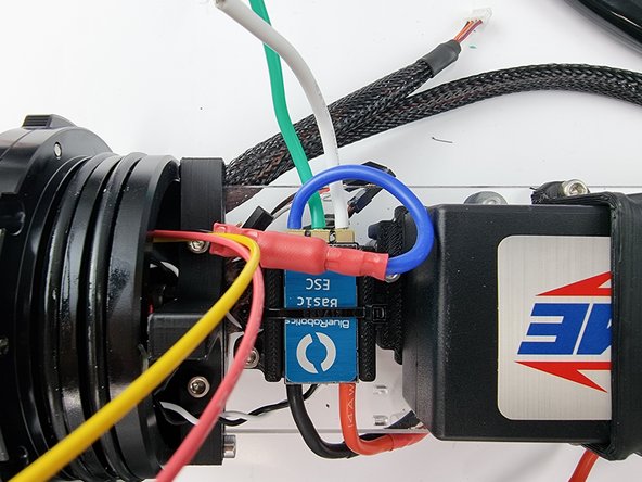
Connect the 2 bullet connectors together to join the black wire from the 3 pin bulkhead connector to the blue wire from the thruster ESC
-
-
-
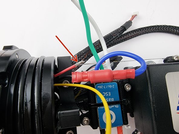
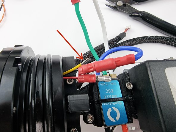
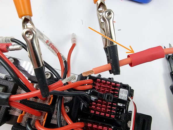
Trim the red wire and strip the insulation from the end of the wire to prepare it for the bullet connector
-
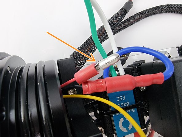
Slide a male bullet connector onto the wire and crimp it into place
-
Give the connector a tug to ensure that it is crimped on properly and not going to slide off.
-
-
-
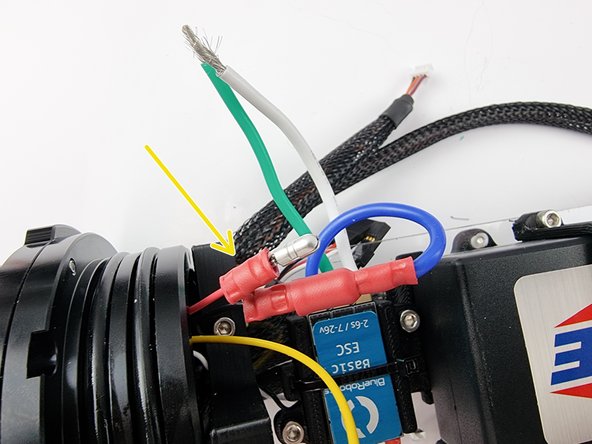
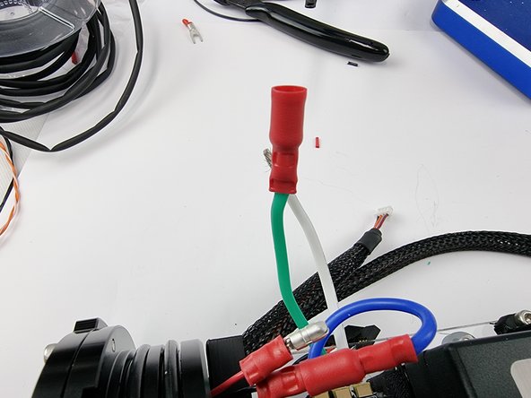
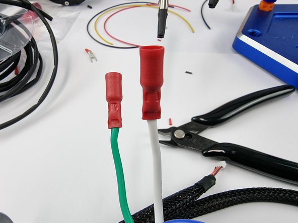
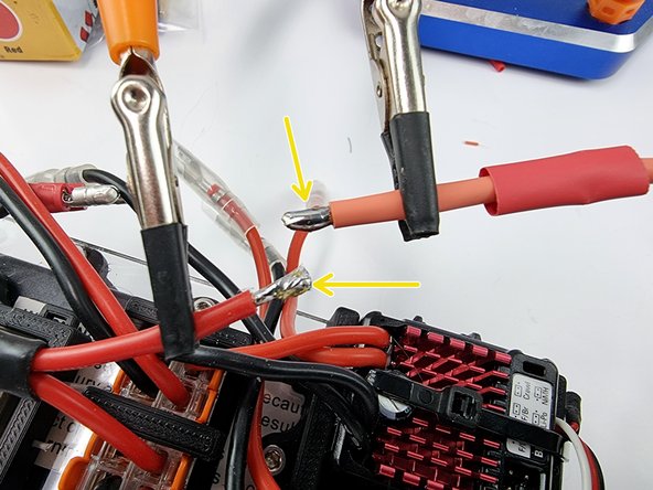
Slide a female crimp connector onto the green wire and crimp into place.
-
-
-
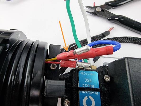
Trim the yellow wire to length and strip the insulation from the end of the wire.
-
Slide on a male bullet connector and crimp it into place. Ensure that you give it a tug to check it has crimped onto the wire correctly.
-
-
-
Slide a female bullet connector onto the white wire and crimp it into place. Ensure that you check that it has been crimped on properly.
-
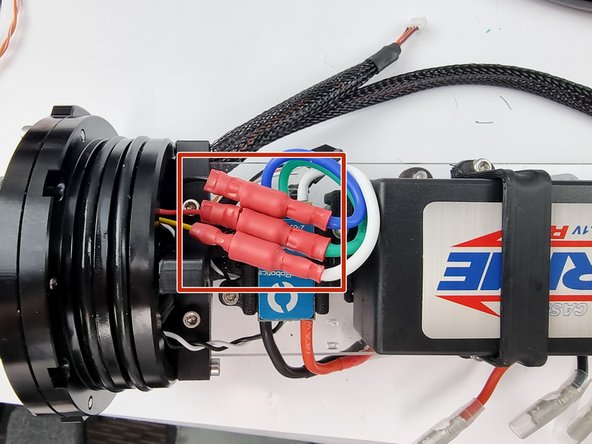
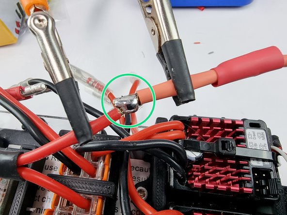
You can now connect the bullet connectors together making sure you connect them in the following pairings
-
Black wire to Blue wire, Red wire to Green wire, Yellow wire to White wire
-
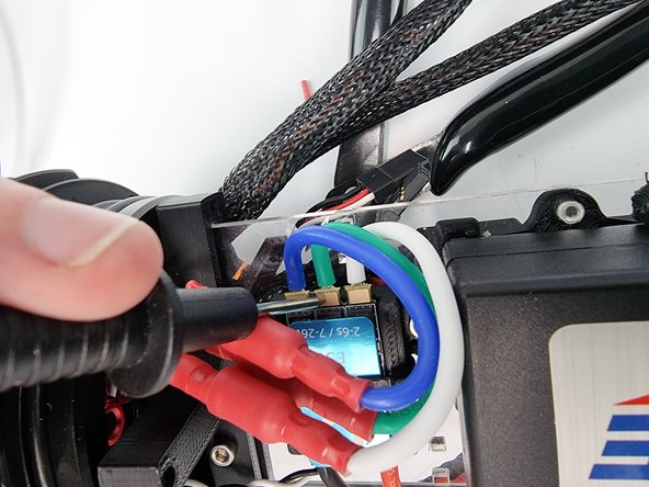
You can check the continuity across the wires by using your multimeter. Touch one of the pads on the thruster ESC and touch the pins in the 3 pin bulkhead connector.
-
-
-
The final step is to wire the battery and power switch.
-
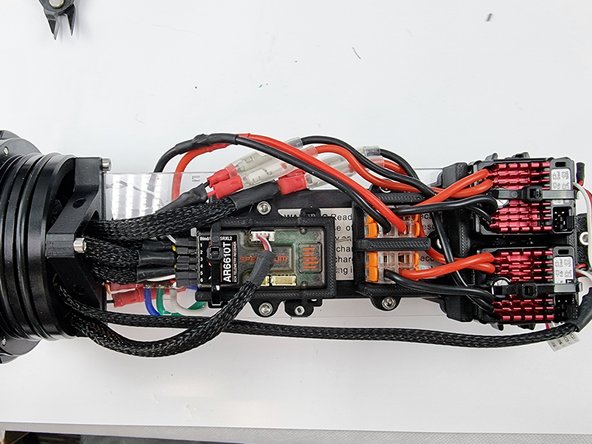
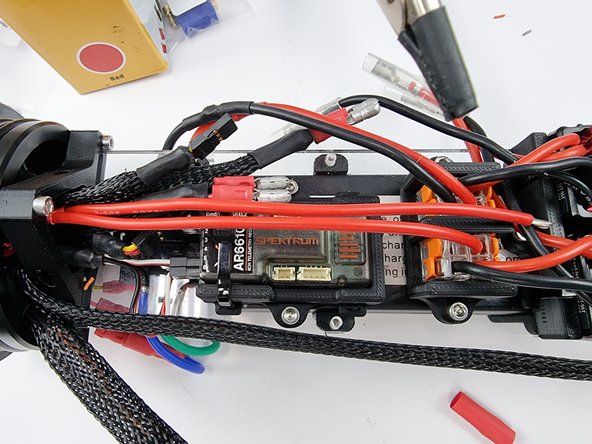
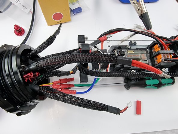
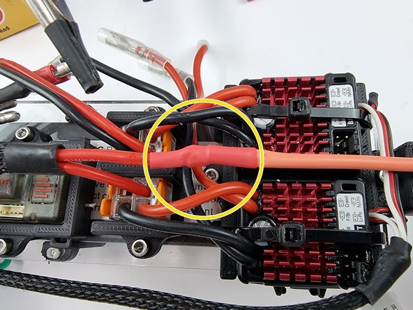
Your Power and Processing Module (PPM) should be looking similar to this.
-
-
-
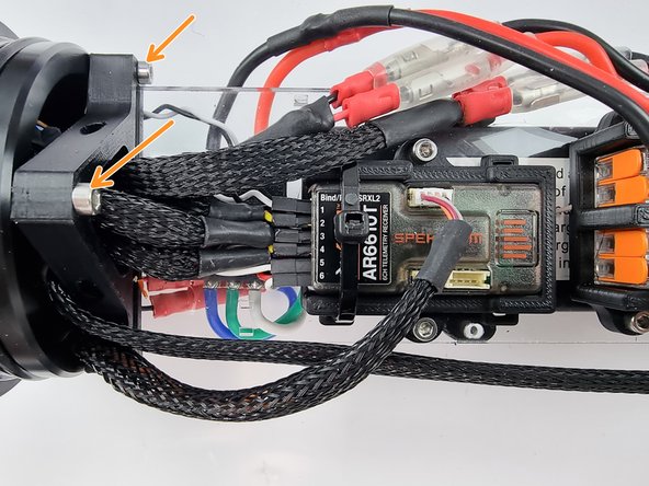
We need to unbolt the support plate mount from the end cap to get access to the power switch
-
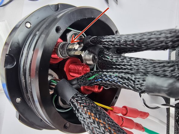
We need to solder 2 wires onto the tabs of the power switch so unscrew the switch out of the penetrator.
-
-
-
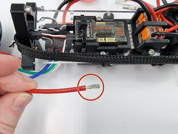
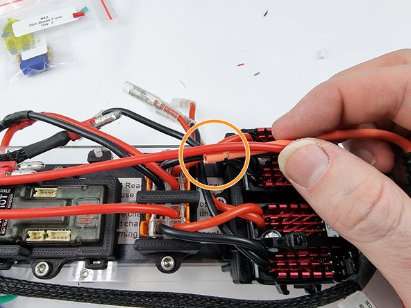
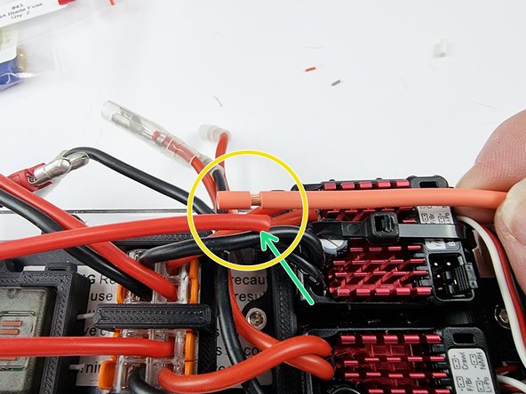
Grab the red power wire and strip the insulation from the end of the wire.
-
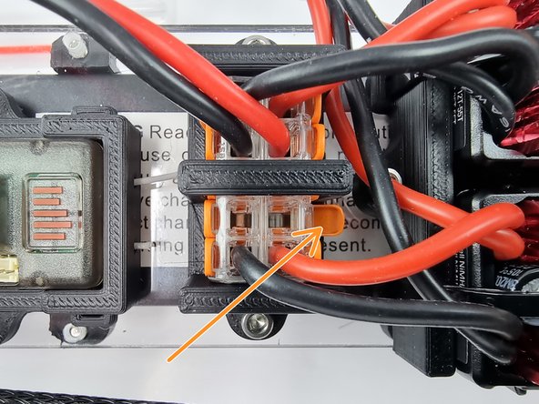
We will insert the end of the wire into the Wago 221 terminal block. Open the lever so that the wire can be inserted.
-
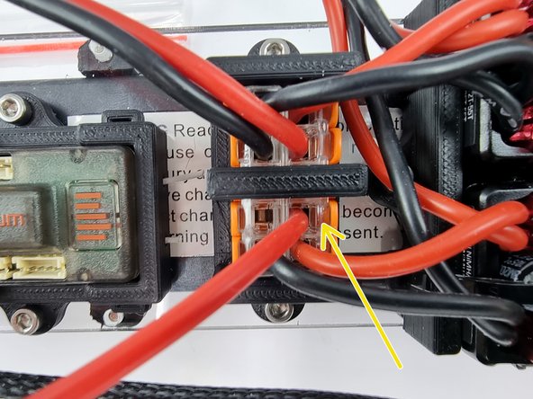
Insert the wire into the Wago 221 connector and lift the lever to lock the wire into place.
-
-
-
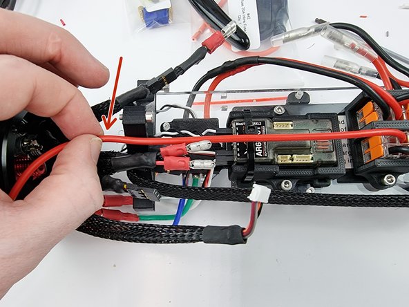
Grab the red wire that was just inserted into the Wago 221 and run it to where the power switch would normally sit to gauge the length at which we need to cut the wire.
-
Cut the wire and strip the insulation from the end of the wire.
-
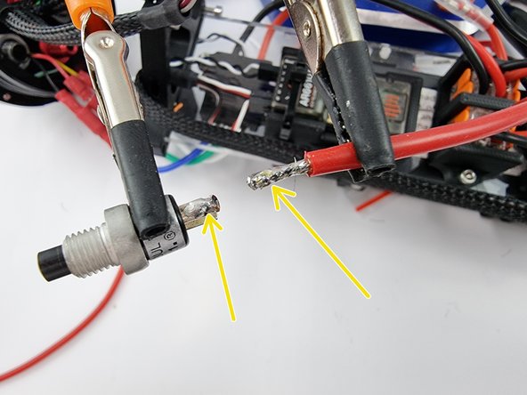
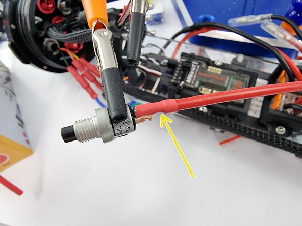
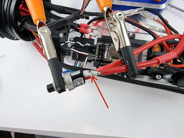
Secure the switch and the wire in place and tin the end of the wire and the tab of the power switch.
-
It doesn't matter which tab you solder this wire to.
-
-
-
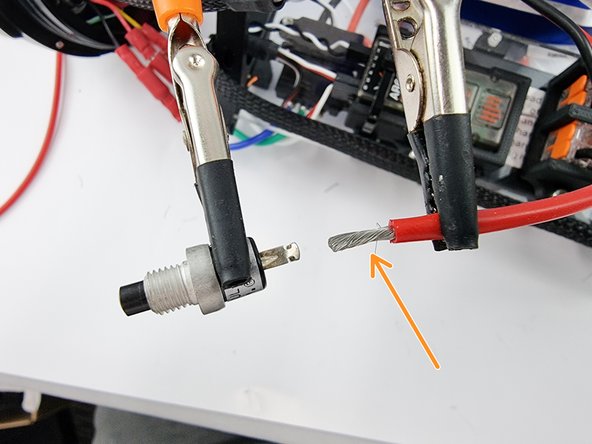
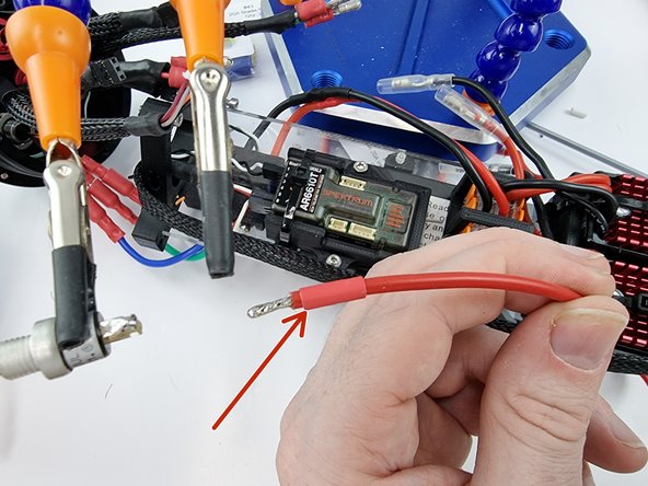
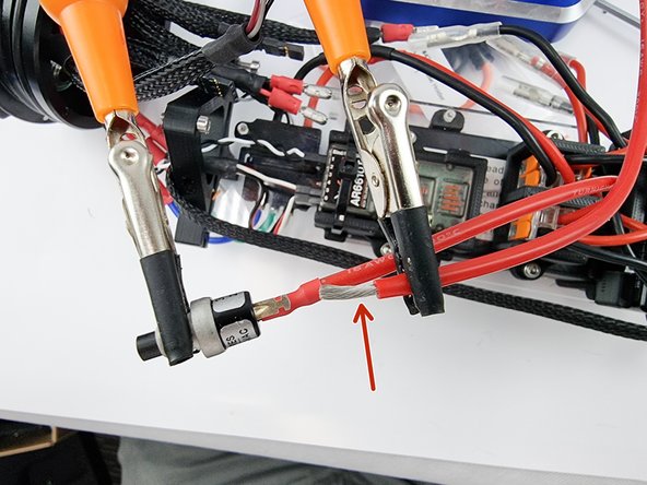
Before soldering the wire to the switch cut a section of heat shrink and slide over the wire.
-
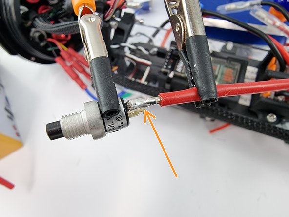
Solder the wire onto the tab of the power switch.
-
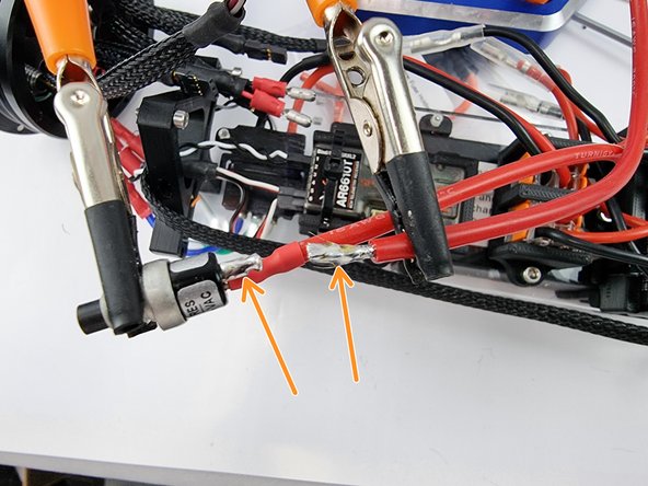
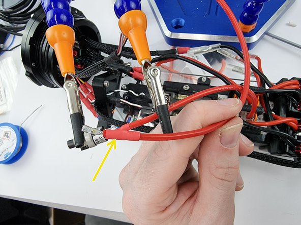
Once the solder has cooled slide the heat shrink over the joint and apply heat to shrink it into place.
-
-
-
Grab the section of red wire that you have left and strip the insulation from the end of the wire.
-
Tin the end of the wire and the pad of the switch with solder to prepare them for soldering.
-
Before soldering them together cut a strip of heat shrink and slide over the wire
-
-
-
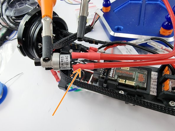
Solder the wire to the pad of the power switch
-
Allow the solder to cool and then slide the heat shrink over the joint and apply heat to shrink the heat shrink into place.
-
-
-
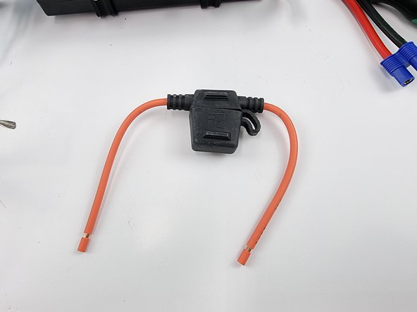
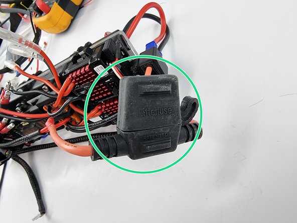
Next is to install the fuse holder on the battery positive line. This will protect the wiring and the battery from drawing too much power if something goes wrong.
-
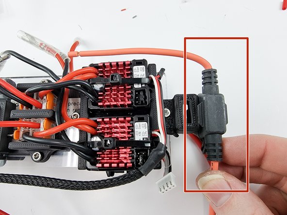
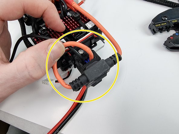
The fuse holder will sit at the end of the support plate as shown.
-
-
-
Grab the wire from the power switch that was just soldered. We will join this with one of the wires from the fuse holder.
-
Place the wires together to gauge the length that you need to trim the wire from the power switch to.
-
Cut the wire leaving enough length to solder them together. Strip the insulation from the end of the wire.
-
-
-
This is how it should currently look. You will have the 2 red wires running to the power switch
-
Optional: if you want to sleeve the wire now is the time to do it before we solder the wire to the fuse holder.
-
-
-
Secure the end of the wire from the power switch and the end of the wire from the fuse holder
-
Before soldering the wires cut a section of heat shrink and slide over one of the wires.
-
Tin the ends of the wires with solder to prepare them to be soldered together.
-
Solder the 2 wires together.
-
-
-
Once the soldered joint has cooled down slide the heat shrink over the soldered joint and apply heat to shrink it into place
-
-
-
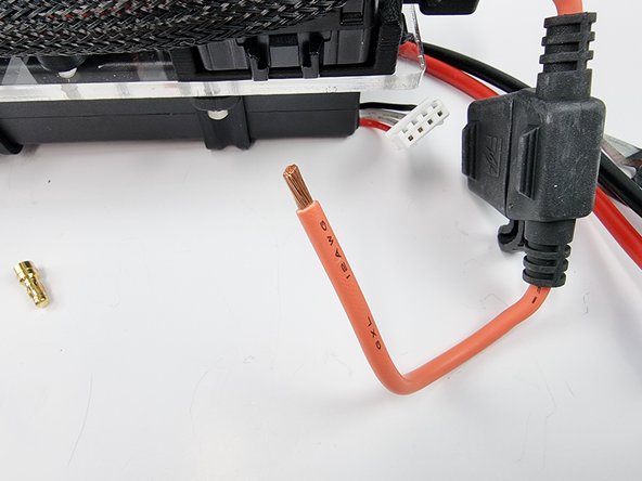
The other wire from the fuse holder is to be connected to the EC3 connector to be plugged into the battery.
-
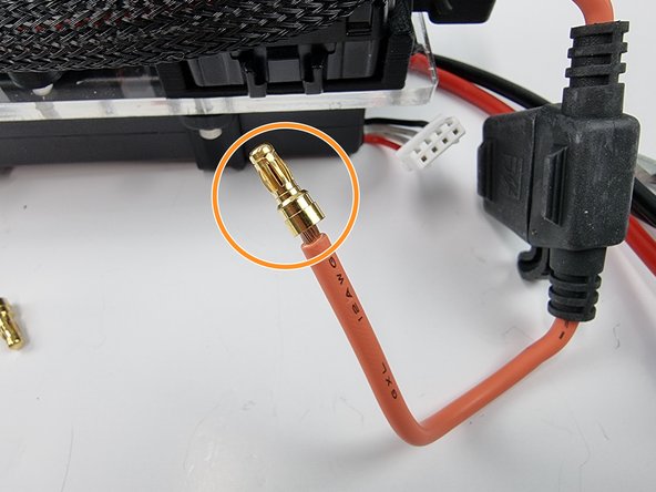
Grab one of the pins from the EC3 connector. The wire from the fuse holder needs to be soldered into the hole in the pin.
-
-
-
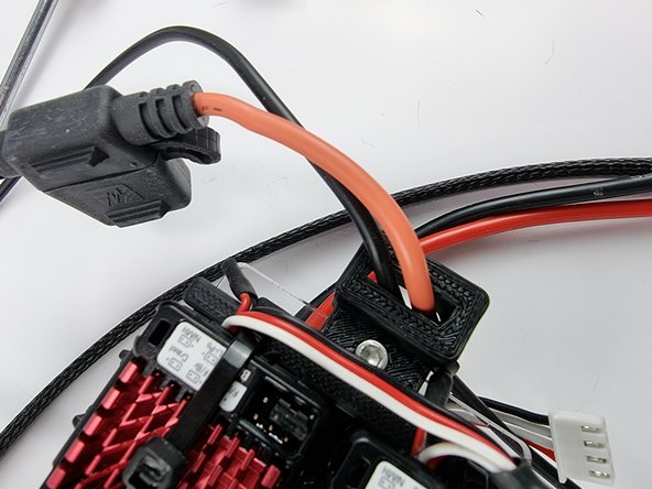
Before we install the pin onto the end of the red wire from the fuse holder feed the wire through the 3D Printed EC3 holder at the end of the support plate.
-
Secure the pin and the wire together so that they can be soldered together.
-
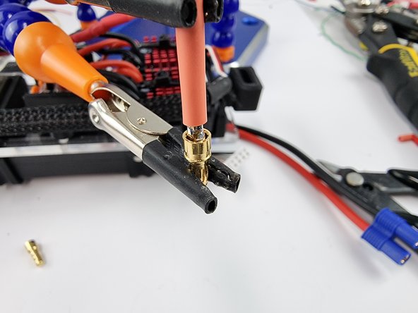
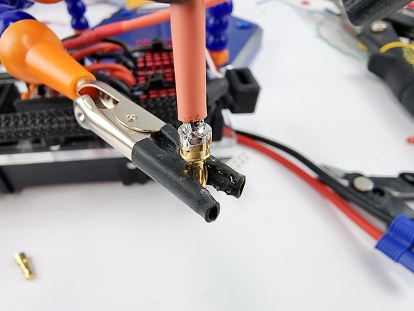
Fill the cavity in the pin with solder to secure and create a good connection with the wire
-
-
-
We now need to solder the other pin from the EC3 connector to a section of black wire.
-
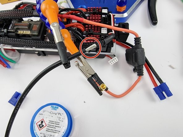
Grab the black wire that came in the kit and strip the insulation from the end of the wire.
-
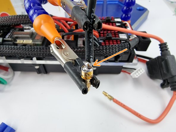
Place the end of the wire into the cavity of the pin and solder to fill the cavity securing the pin to the wire and creating a good connection
-
-
-
Next is to insert the pins into the plastic part of the EC3 connector.
-
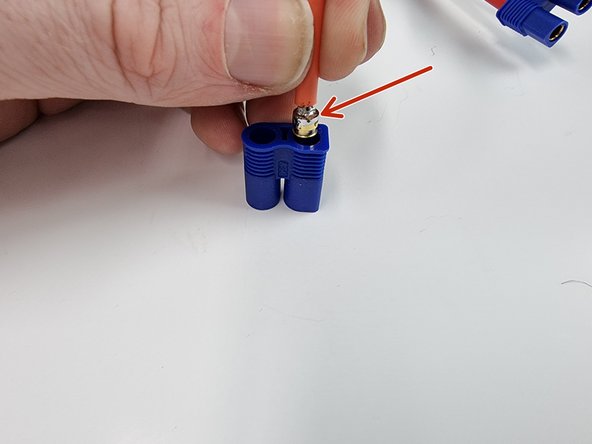
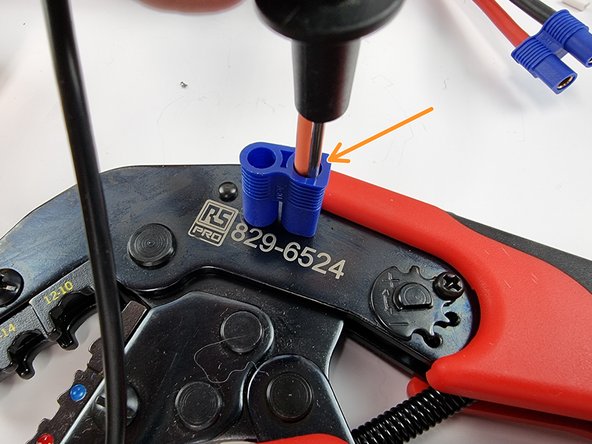
Insert the red wire into the hole with the flat side.
-
Put the connector on a solid surface and use something small to push the pin into the connector until you hear it click into place.
-
-
-
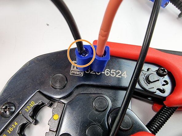
Now insert the pin on the black wire into the other hole of the connector.
-
Push the pin into the connector making sure it clicks into place.
-
-
-
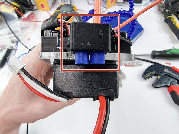
Once the connector has been assembled slide it into place in the 3D Printed holder.
-
The fuse holder will sit at the end of the support plate as shown. If you want you can cable tie it in place if you like.
-
-
-
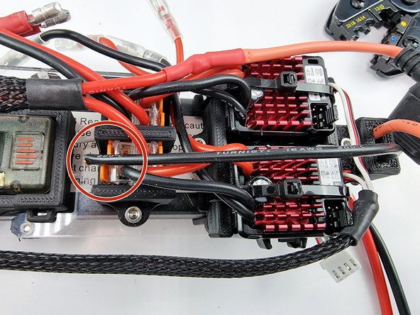
The black wire can be trimmed to length. It needs to be connected into the Wago 221 terminal block that has the other black wires in it.
-
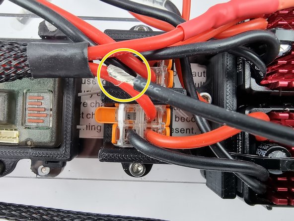
Strip the insulation from the end of the wire and twist the strands to prepare them to be inserted into the Wago 221 terminal block.
-
-
-
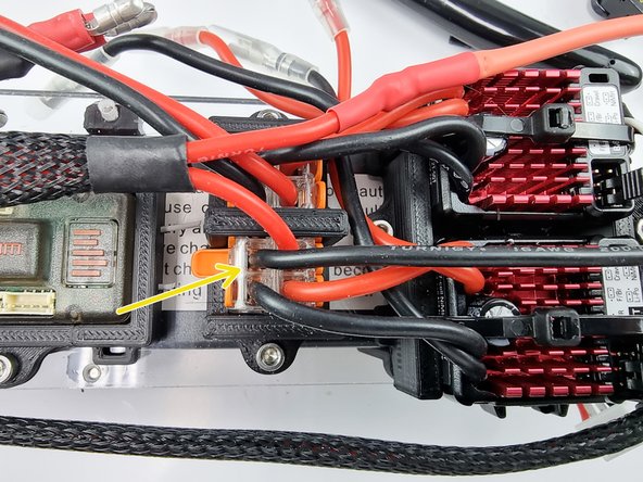
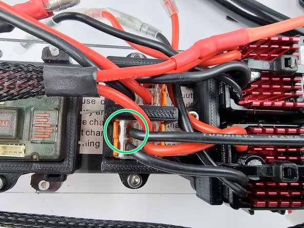
Open the lever on the Wago 221 terminal block and insert the black wire into it ensuring it is inserted all the way
-
Once inserted lift the lever up to lock the wire into place.
-
-
-
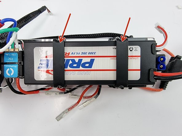
Install the LiPo battery onto the support plate and secure it using the 3D Printed straps.
-
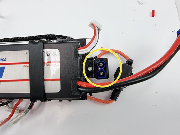
You may now plug in the battery to the EC3 connector. Ensure that you have the power switch wound out a bit so that it doesn't power on when you plug the battery in.
-
-
-
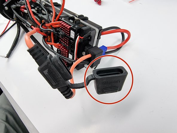
Open the cap on the fuse holder
-
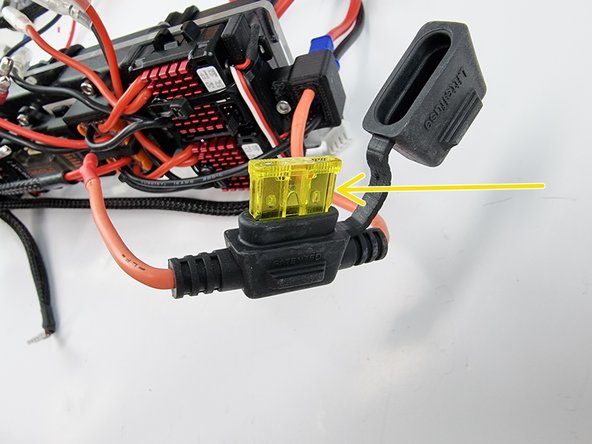
Install the 20 amp fuse into the fuse holder
-
Close the cap on the fuse holder.
-
-
-
The wiring is now finished for the PPM. You may test it now by turning the power switch on.
-


