Introduction
This requires soldering of wires. When the power wire system is completed, you can connect it to the control system. To connect the power wires to the control system:
Tools
Parts
No parts specified.
-
-
Watch the informative video, taking note of the principles behind wire crimping and the techniques featured that can be applied to your ROV or Submarine build.
-
-
-
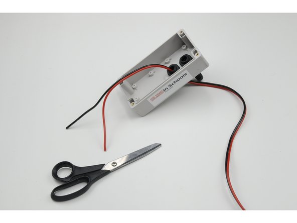
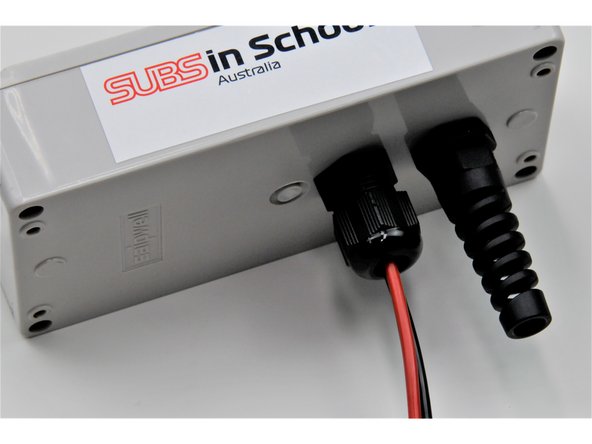
Push approximately 30 cm of the red and black wire (the side without the fuse) through the short stress relief.
-
-
-
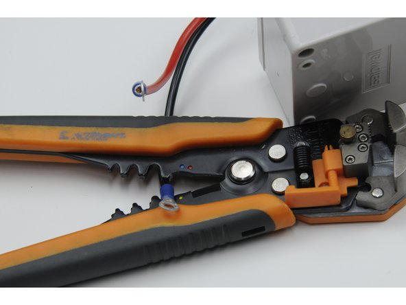
On the 30 cm of wire inside the control box, pull apart 8 cm of the red wire and black wire (separate the two joined coloured wires).
-
Strip 0.75 cm from the end of each wire.
-
-
-
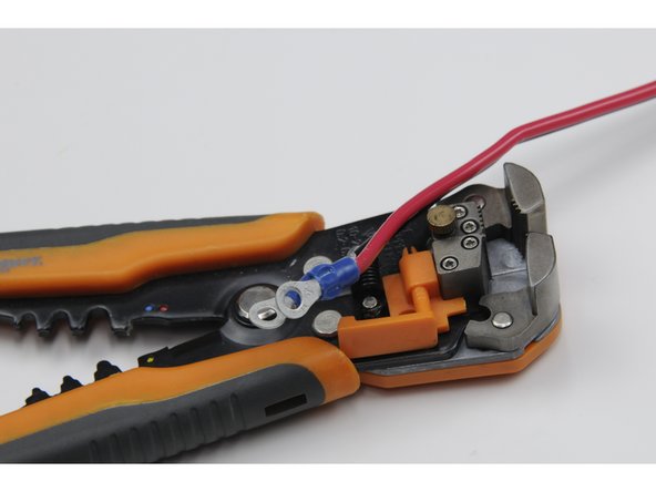
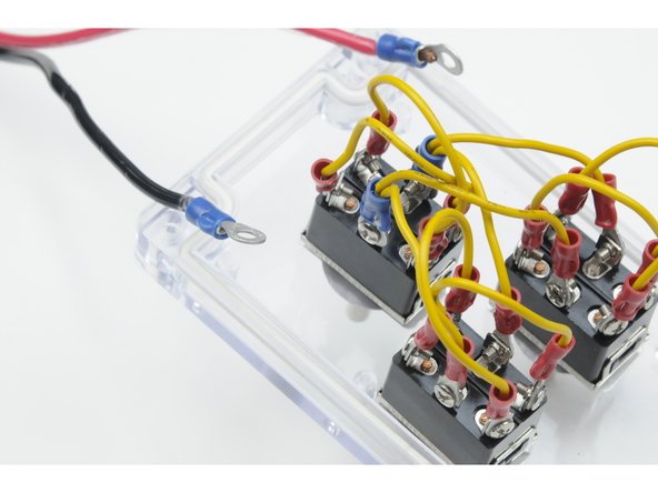
Crimp a blue ring terminal over the end of both the red wire and black wire.
-
-
-
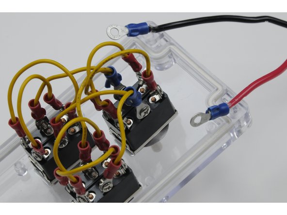
Set your clear plastic faceplate upside down to access the bottom of the switches.
-
Carefully unscrew the centre, right post (post #2 or post #5, on the right side of the switch as you are looking down at it) screw on ONE switch only.
-
This post should already have a jumper wire attached.
-
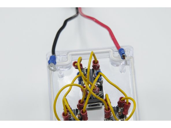
Attach both the jumper wire and the blue power wire to this post. Use the screw to secure both ring terminals and both sets of wires to the post.
-
-
-
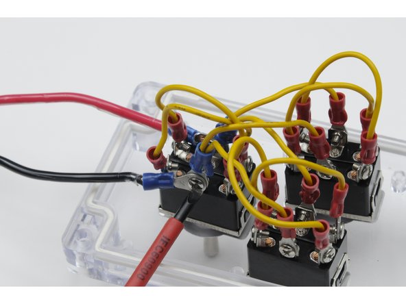
Carefully unscrew the centre, left post on the same switch. This post should have the other power jumper wire attached.
-
Attach both the jumper wire and the blue power wire to this post. Use the screw to secure both ring terminals and both sets of wires to the post.
-
-
-
Design note: The jumper wires will bring the 12V+ from the red power wire to all three switches. The jumper wires will bring the GND from the black power wire to all three switches.
-
Make sure that the red and black power wires are attached to the two different jumpers.
-
-
-
Once both the red and black wire are secured to a switch, pull the any excess power wire back out through the small stress relief. Tighten the small stress relief nut over the threads to secure the power wire in place.
-
Design note: The side of the switch that the red and black wires attach into controls polarity; which way the motor runs when you push your switch forward. If all three of your motors run in the opposite direction as desired, you can switch the sides of the wires, and the polarity will change (motors will now run in opposite direction).
-
-
-
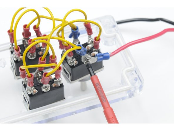
You can test the power system by tracing the voltage through the system.
-
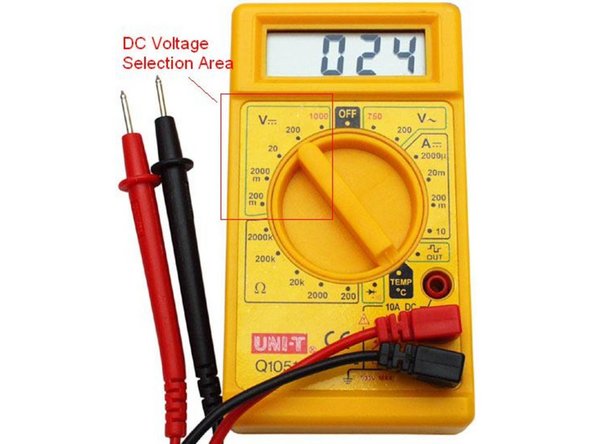
Set the multimeter on DC volts and connect the power tether to a power source.
-
-
-
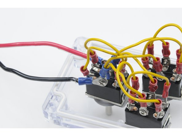
Touch the red multimeter lead to any one of the red dots shown in the picture and black multimeter leads to any one of the black dots.
-
All possible combination of red and black should read the source voltage.
-
If you are reading zero volts then check the fuse has been installed and is good.
-
If you get a voltage reading that is bouncing around check for a loose screw connection on the DPDT switches.
-
If you have good voltage reading (same as source voltage) on all three switches, your control box is complete. Don’t close up the box yet, however, there are a few more wires to add.
-