-
-
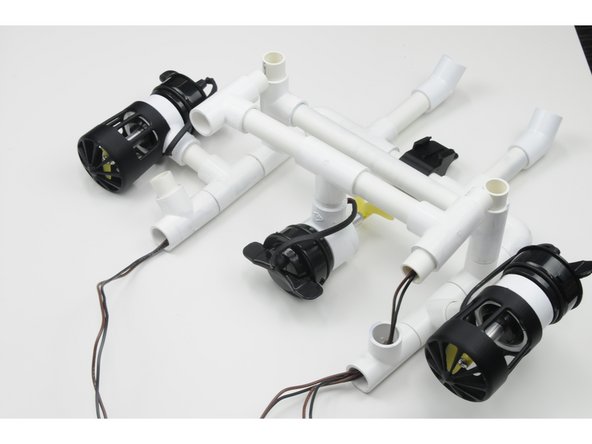
Collect the three motor units, and identify the area to drill; as shown in the accompanying image.
-
-
-
Collect a 4mm and 8mm drill bit.
-
-
-
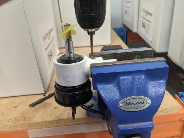
Mount the motor assembly in a vice, ensuring the surface to be drilled is held at a 90* angle.
-
-
-
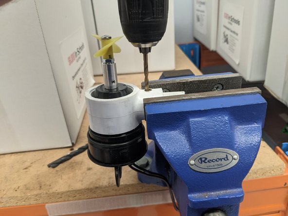
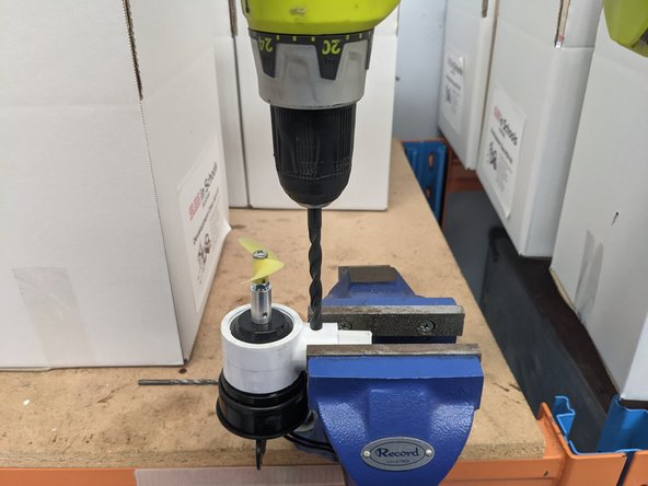
Pre-drill the hole with the 4mm drill bit, ensuring the hole is drilled as perpendicular as possible to the motor mount.
-
Use the 8mm drill bit to enlarge the hole.
-
-
-
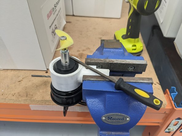
Use a small hand file to clean up any PVC shavings or sharp edges from the hole.
-
This will help prevent the external section of the wires rubbing, and make for a neater build.
-
-
-
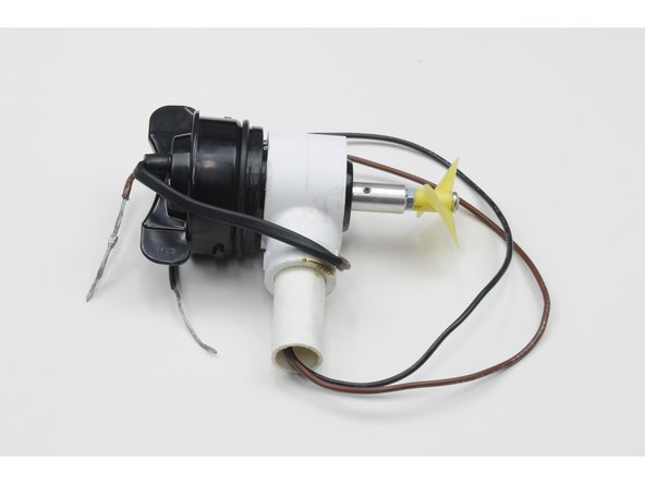
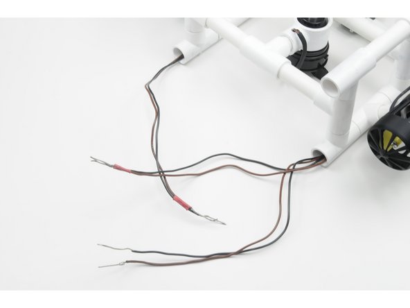
Run the wires through the hole and measure the length of wire that remains on the outside of the unit.
-
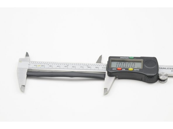
Cut the appropriate length of heat shrink to match the length of external wiring.
-
This should be approximately 100mm.
-
-
-
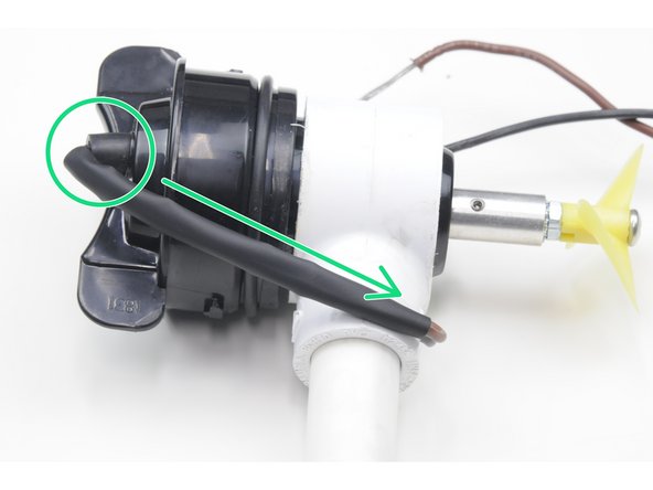
Slide the heat shrink over the wires, ensuring it is the right length.
-
To reduce the amount of visible cables, we suggest running the wires from the side to the back of the motor mount as shown.
-
-
-
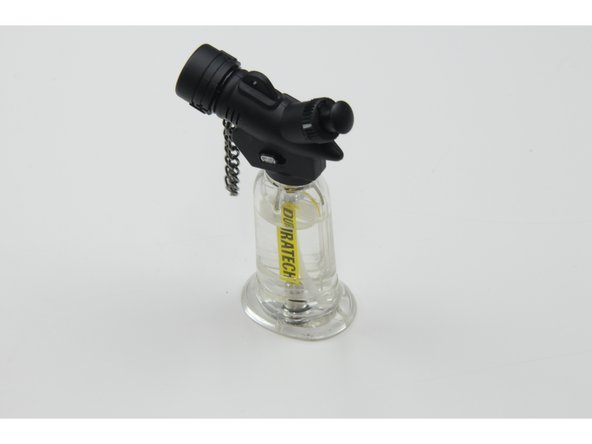
Using the heat gun, or alternate heat source, secure the heat shrink in place.
-
-
-
Cut three short sections of a light coloured heat shrink, and mark them with an 'L', 'R', and 'T' - (Left, Right & Top).
-
Ensure the marker used does not rub off easily. A ball-point pen can be used to mark and press the letter into the heat shrink.
-
Secure these three sections of heat shrink to their associated motor wires, near the end of the wire.
-
This will allow you to identify the pairs of wires once they are routed through the frame.
-
Masking tape can be substituted in place of these tags if necessary.
-
-
-
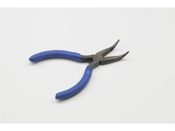
We recommend using a small set of needle nose pliers for the following steps.
-
-
-
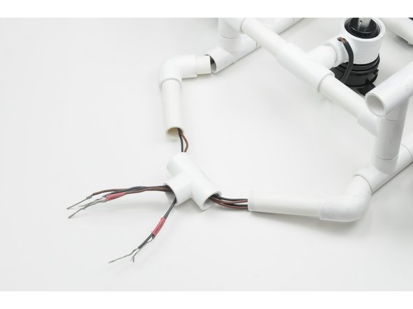
Push the wires through the hole, and work them through the frame of the ROV.
-
You may find it easier to break the ROV frame into sections, or, if necessary, individual pieces to route the wires.
-
Use the long-nose pliers as necessary to pull the wires through the frame. Making sure not to pull the heat shrink tag from the wires.
-
-
-
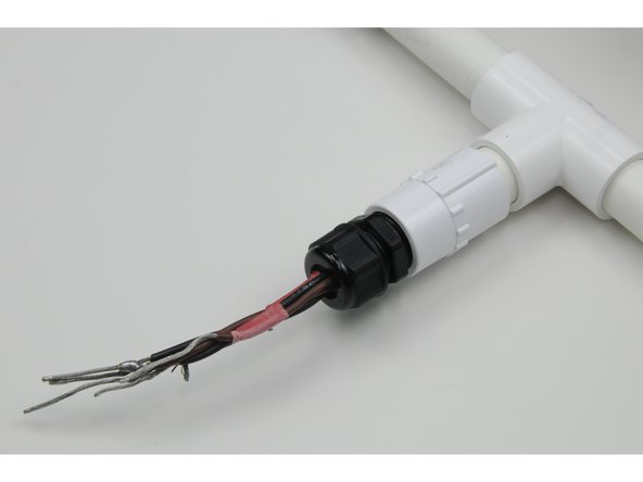
Route the excess wire through the rear stress relief provided.
-
Almost done!
Finish Line


