-
-
Unbox the thruster.
-
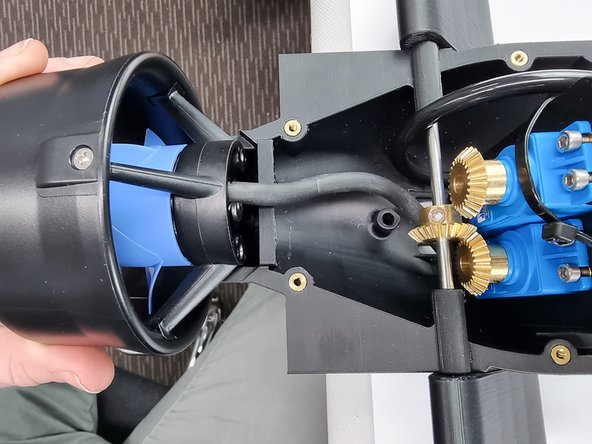
We will remove the back shroud on the thruster to allow us to mount it to the bottom aft cap.
-
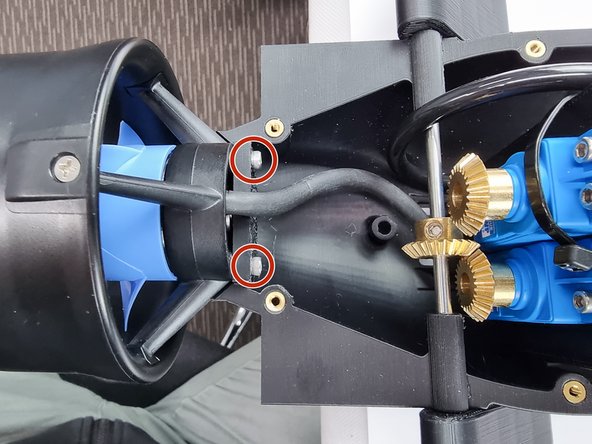
Using a 2.5mm Hex Key remove the 2 bolts from the shroud.
-
Once the shroud has been removed keep the 2 bolts as they will be used to mount the thruster to the bottom aft cap.
-
-
-
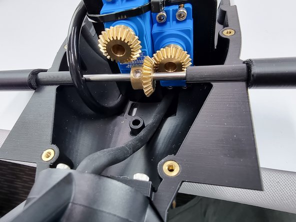
Feed the wire through the slot under the servos
-
Pull the wire through to remove the slack of the wire
-
-
-
Move the thruster into position on the bottom aft cap.
-
Insert the 2 bolts that were removed from the shroud into the 2 holes in the bottom aft cap to secure the thruster in place
-
-
-
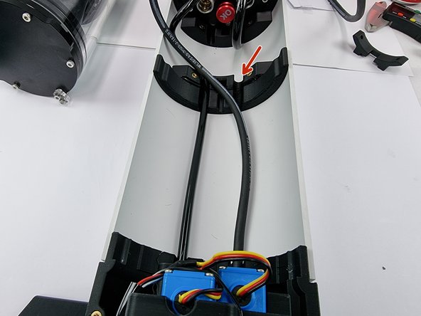
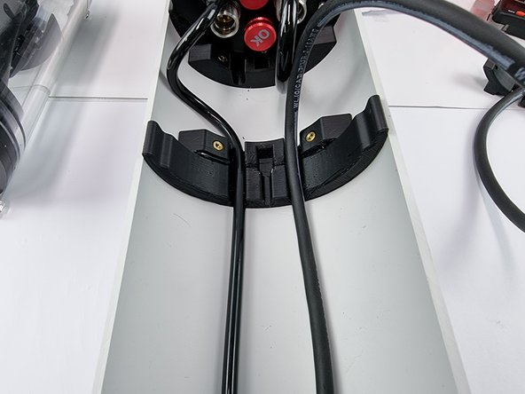
Remove the slack from the thruster cable by feeding it through to the front of the Sub.
-
Straighten the cable out and insert it into the slot in the hull support.
-
-
-
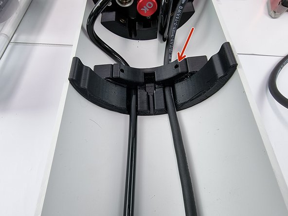
Place a cable cover over the cables in the hull support brace to secure the cables in place.
-
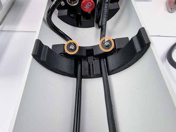
Insert 2 x 8mm socket head cap screws to fix the cable cover in place.
-
-
-
Unpack the 3 pin cobalt connector
-
We need to roughen the inside of the connector shell to allow for better adhesion of the potting compound. Using a piece of sandpaper sand the inside of the connector shell.
-
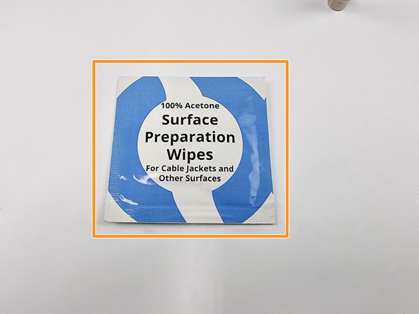
Now wipe the inside of the connector shell clean with the surface preparation wipes or acetone if you don't have the wipes.
-
-
-
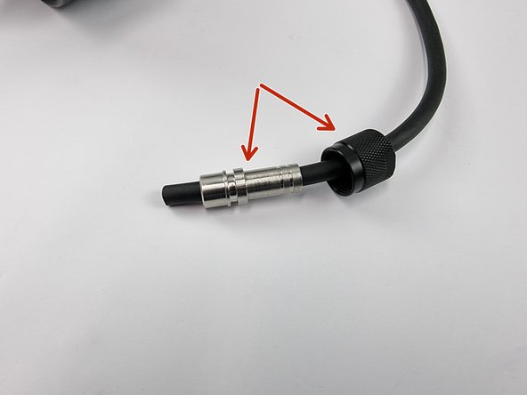
Slide the locking sleeve (Nut) onto the thruster cable followed by the connector shell
-
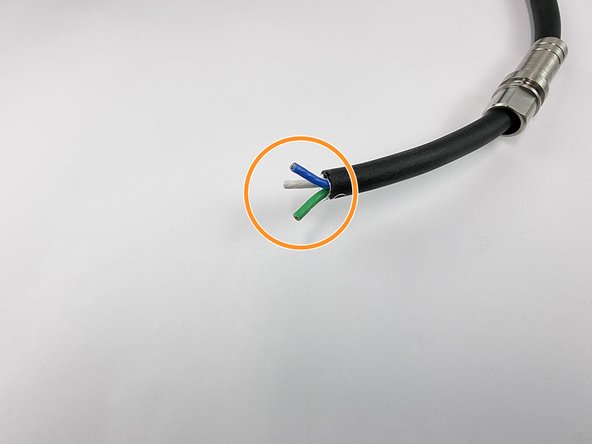
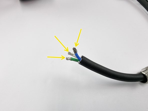
Strip the outside sheathing from the thruster cable.
-
Strip the insulation from the end of the 3 wires
-
-
-
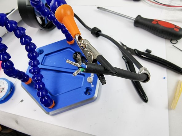
Support the cable to prepare it for soldering.
-
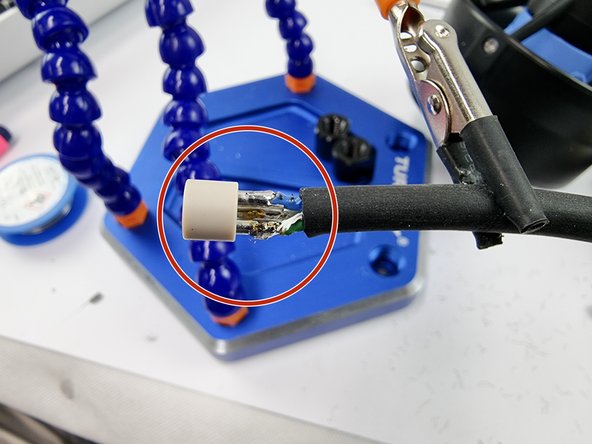
Insert the wires into the sockets on the Connector Insert and solder them in place.
-
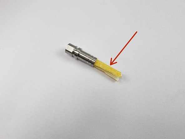
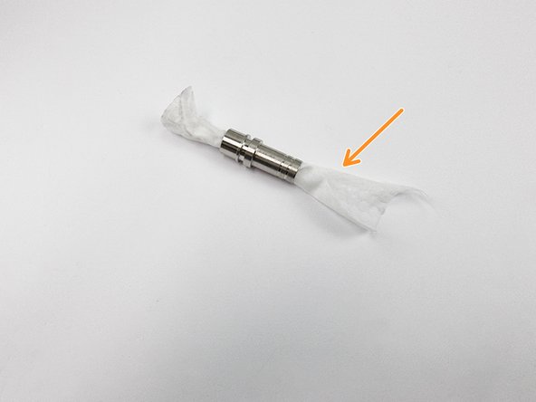
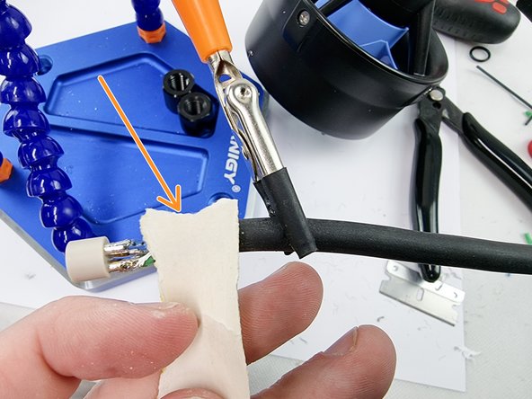
Abrade the last 3 cm of the cable jacket with sandpaper and clean with acetone to prepare it for potting. From this point on, be careful to keep this part of the cable jacket clean.
-
-
-
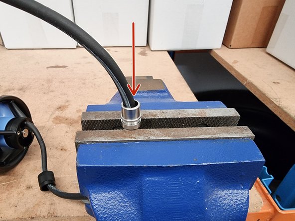
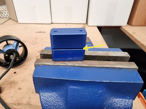
Place the connector shell into a vice.
-
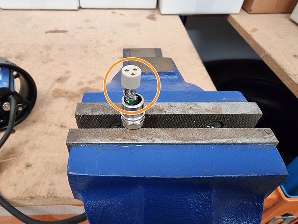
Feed the cable through the connector shell until the connector insert reaches the shell.
-
Visually inspect for any stray strands of wire or solder. Once the Connector Insert is pressed into the Connector Shell, there will be no way to fix any electrical shorts.
-
-
-
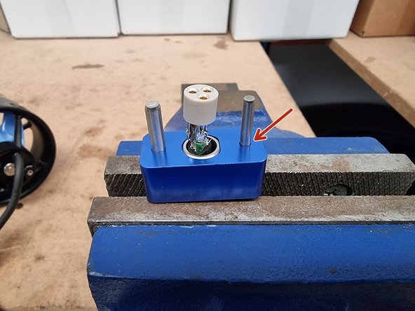
Place the lower half of the Termination Tool over the Connector Shell, aligning the flats.
-
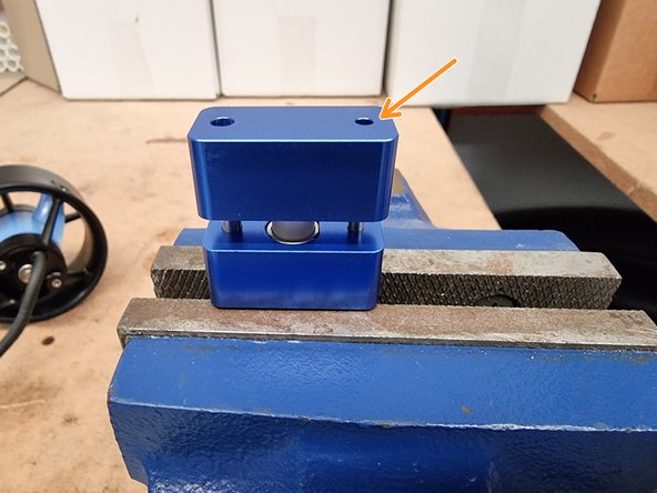
Slide the upper half of the Termination Tool onto the lower half of the Termination Tool. Insert the pins on the upper half of the Termination Tool into the sockets on the Connector Insert.
-
Using a drill press or a soft hammer, push down or gently tap on the upper half of the Termination Tool until the Connector Insert is pressed completely into the Connector Shell.
-
-
-
Now that the connector has been assembled we now need to waterproof it by potting the back side of the connector.
-
Follow this guide that steps you through the potting process. Potting Guide
-